Short on cash, got lots of time, and want/need a new piece of DJ gear custom to your needs? It’s time to go DIY! For about $100 you can build your own MIDI controller. Watch the full how to video from guest contributor Kyle Mohr and read the full construction guide inside.
DIY MIDI Controller Shopping List
First you’ll need to purchase all of your tools and materials. I’ve found the best prices and parts are usually sold on eBay from retailers based in China, but they tend to sellout fast and shipping to the States takes 2-3 weeks (this will, however, give you plenty of time to get your enclosure ready and board programmed). But, to make things easier I’ve provided many links for Amazon and US retailers.
Click the below sections to expand the lists:
PartsEnclosure Finishes
*Note: These are not necessary, but if you have a wood enclosure they help make things look a lot nicer
Note: It will put you way over the $100 budget if you need any of these tools, but if you plan to do more projects in the future they certainly will come in handy and you can always buy them really cheap on eBay and Amazon.
- Soldering Iron
- Rosincore Solder *Any Rosin-core solder should do, this is just what I used
- Soldering Flux
- Drill
- Hobby Files
- Drill Bit set
- 24mm or 1in Spade Bit
- Liquid Electric Tape
- Gorilla Glue
- Wire Cutters
- Plier set
- Small Screw Driver Set
- Hot Glue Gun
- Hot Glue Sticks
- Mini Hack saw
- Box Cutter
- Dremmel with wood cutting bit
- Sandpaper
- BONUS: here’s a great video on tools you need for electronics projects
DESIGN
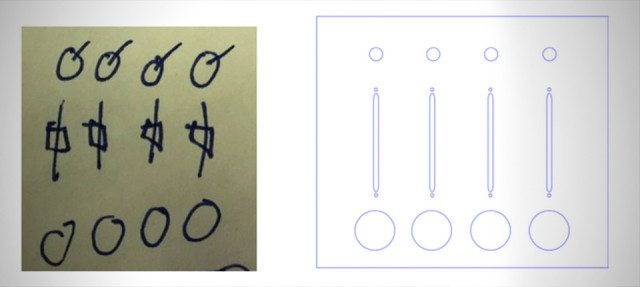
This is my awful drawing on a post-it note, but it suffices as an ideal layout and sketch. I followed it up using Adobe Illustrator to make a to-scale blueprint. Download the PDF and EPS files here. This was designed for 4 potentiometers, 4 faders and 4 arcade buttons, but you can certainly swap them out for other components.
For the buttons, you’ll need a 1 inch or 24mm spade bit and you should aim for using a 5/16 bit for the potentiometers. Make sure to leave plenty of space between your components and do not overcrowd the layout. This will result in broken enclosures and tight areas for soldering. You don’t always have to be this exact, you can always just take a marker and ruler, measure distance between components and make sure to keep the distance the same, and mark up the back or inside of your enclosure with drill/cut spots.
Case Building
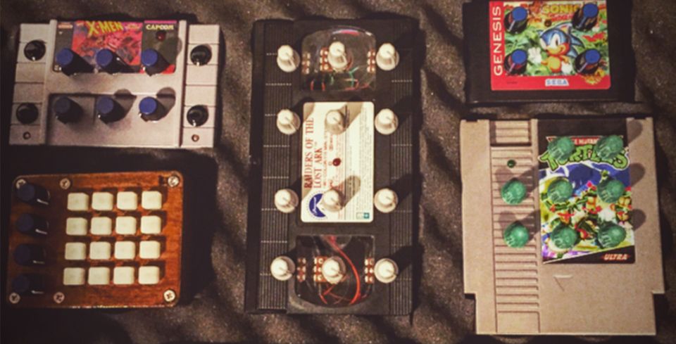
Once you’ve finalized your layout its time to “build” or make room for your components. You can use anything for an enclosure: an old VHS tape; plastic lunchbox; retro video game cartridge; a wooden box; or even 3D print your own. The main point of DIY besides saving some money and learning what is really inside your gear, is to customize it to be truly original.
Before you start drilling holes be sure to measure all components and their clearance!
When drilling holes for components in the enclosure, especially with thin wood and plastic, to keep it from cracking when drilling, make sure to choose about 6-7 drill bits from very small to your final size.
For LEDs I always use this guide (look under “Making holes if needed”). This will help you slowly get to your desired size without putting too much tension on the material causing it to crack, chip or break. The key is to drill at slow speeds, and gradually go up to the size you need. If something starts to crack or chip, quickly stop and put your drill direction in reverse. Try using it in reverse for a bit to clean up the cut.
Once you’ve drilled, cut and punched your way through the enclosure its time to clean it up. Don’t worry, it always looks like a hack job. The key is to take your time. Try to drill and mark up the inside (spots people won’t see) and even place a spare board under your enclosure that you can drill into. This also helps to reduce tension on the enclosure.
Now if you used plastic, you’re in luck! You’ve just saved yourself days, seriously! For plastic you can simply use the hobby files to file off any jagged edges, or frayed pieces of plastic, which are blocking the holes.
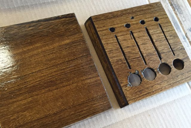
Want to make an awesome wood enclosure?
If you used wood, get ready to go all Ron Swanson on your project. Most cheap wood like we’re using here looks, well, cheap! So how do we class up that piece of junk to look like a custom cut piece of expensive furniture?…Stain!
- I highly recommend pre-stain. It will help the stain spread evenly, especially on cheap/thin wood and prevents spots.
- After 5-15 minutes it’s time to add that stain. Just take a rag, dip in stain and apply to your enclosure. I like to use Dark Walnut. Apply and then immediately remove, and repeat this process a few times. This will give it a more rustic/steampunk look, but if you want something more solid, don’t wipe the stain away, just apply a lot and leave it to dry.
- After a day of drying, apply polyurethane with a brush. Fully coat all sides to protect your enclosure from scratches, and protect, and even strengthen the wood. I suggest brushing it in the direction of the wood grain.
- Let dry for 24hrs, then repeat to your liking. I recommend 3 coats, 24hrs between each coat.
- After the final coat, let dry for 72hrs before adding component parts! This avoids putting my components into a sticky polyurethane mess.
COMPONENTS
Now that you’ve finished your DIY MIDI controller layout and enclosure, it’s time to add your components to the faceplate. Buttons usually just pop in, but some will require a fastener or nut to be placed on the back to secure it (if there is a little resistance, don’t force it, just take your hobby files to it a few times then try again).
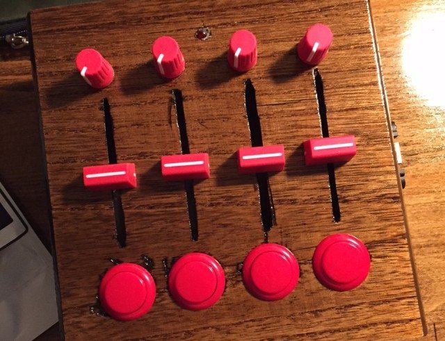
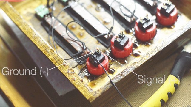
Potentiometer knobs will then be placed in with washers and nuts. These should cover any jagged edges you may have from drilling. Tighten with pliers. For linear potentiometers (aka faders) make sure you have the number 1 (power) on the top. This may vary depending on make and model (feel free to test using a breadboard). 2 is usually your signal, and 3 should be ground. Then secure to the faceplate with your M2 screws.
To protect the components, add your Chroma Caps to faders and pots now (or any off-the-shelf caps as well, we just like those the best).
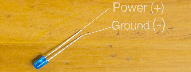
To add the LED, flip over the faceplate or top of enclosure and put your LED into the hole(s) you drilled for it. You may need to use your hobby file again for this to make sure the LED fits just right. Afterwards, push it through just enough to see the tip on the other side. Using a toothpick as an applicator line the circumference of the LED with Gorilla Glue. Once hardened it will ensure your LED doesn’t fall back into the enclosure. Don’t use hot glue, it may melt the LED’s plastic.
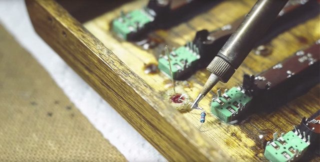
Soldering Your Components
Once the glue on the LED is dry, start the soldering process. This make all of the connections from your components to the circuit board, which will then relay the message to your computer or iOS device (oh yeah, this will also work with your iPhone/iPad)!
First you’ll need your Rosin-core solder (way safer than lead-based solder) – I use and recommend .050”-Diameter 63/37 Rosin-Core Solder.
If you haven’t soldered before there is a wealth of tutorials on YouTube. Here are a few of my favorites. Trust me, its not complicated at all, anyone can do it. Just take your time and pay close attention to what you’re doing.
Turn on your soldering iron and let it heat up for a few minutes. Grab your jumper wires. I use these instead of your average spools of wire because they have a single pin at the end instead of braided wire that is quite difficult to push through a hole. They are much more efficient since with normal wire you have to cut, strip, and heat shrink it every time. I also tend to pre-bend them all at 90 degree angles and trim about ¼ off of them to make sure they fit in any enclosure and the Teensy board.
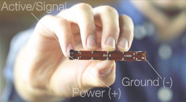
Let’s start from the top and work our way down. First make sure each of your jumper wires will reach from each component to the next, and matching colors is always helpful. I like to use dark colors (black or blue) for the ground line and bright colors (red, orange, yellow) for power while using mild colors (green or white) for the signal line. For D-Shaft potentiometers you want to be certain your pins are on the bottom, this will ensure your knobs fit and that once wired they will be going in the proper direction.
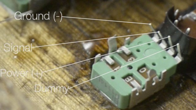
For potentiometers you have 3 lines, ground, active (your analog signal which identifies where the position of your potentiometer is) and your power. They also usually go in that order when looking at the pins, a 4th pin is usually just a dummy pin and will not be used for our project.
Since we only have 1 power and 1 ground point to solder on the Teensy board we need to chain all of our grounds together then all of our power together. Once complete, we need to run that power and ground from the last pot to the first fader, which is soldered and treated as if it was a potentiometer. Follow the guide below.
Once that is complete, run the ground only from your last fader to your buttons. The other point on buttons is your active/signal line.
Solder the active line from each component, 1 single wire from each button, knob, and fader. The Teensy board has built in pull-up resistors that we will access using the Sketch we upload when programming the board so we do not need resistors soldered to the buttons active line.
Next, solder a 220 ohm resistor to the (+) powered pin of the LED, this is to ensure it doesn’t blow out from too much power. Then connect the other side of the resistor to a positive pin on the closest pot. We will then solder the short LED pin (ground) to the closest pots ground pin.
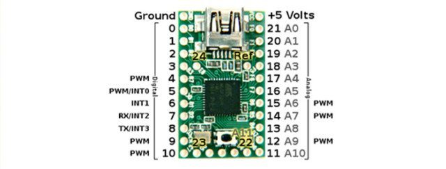
For the last bit of soldering, run the active line from every pot and slider to Analog pins A0 – A7. Where as the active line of each button will be soldered to the Digital pins on the other side of the board B0-B3.
Programming Your DIY MIDI Controller
Setting Up Teensyduino (Arduino + Teensy)
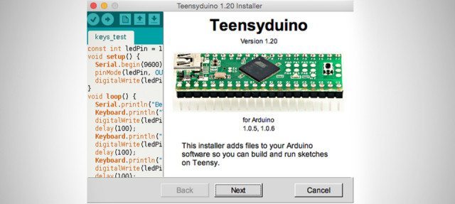
Teensyduino is an add-on for Arduino Uploading Software that enables the Teensy board to be used in the Arduino programming environment. Before we get started you will need to:
- Download Arduino Software *Certain versions of Teensyduino are only compatible with certain versions of the Arduino Software. On the Teensyduino download page this is specified. As of August 2015, “Teensyduino 1.24 supports only Arduino version 1.0.6 and 1.6.1 and 1.6.3 and 1.6.4 and 1.6.5”.
- Download Teensyduino + follow the install instructions on this page (be sure to install all the libraries!)
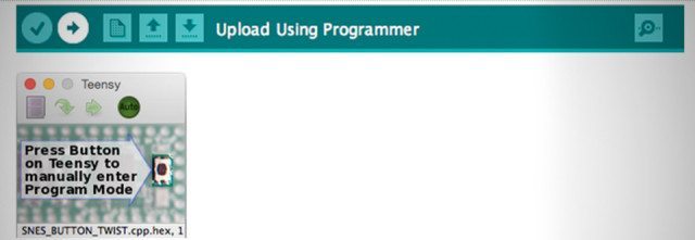
STEP 1: Plug your Teensy board into the USB port on your computer. After plugged in an orange light on the Teensy should be flashing on and off every second. This is called the ‘blink’ sketch – The Teensy board comes pre-loaded with it.
STEP 2: In the menubar, select Tools->Board->Teensy 2.0.
STEP 3: Also in the menubar, Tools->USB Type->MIDI
STEP 4: Open a sketch file (download mine here). This sketch is set to 8 analog pots (the faders are treated as a knob/pot when it comes to the code) and 4 digital buttons. If you have more knobs or faders, simply change the number here:
If you wish to add more buttons, there is a little more work, but it isn’t too complicated to fix.
STEP 5: Click the upload button (right arrow) to upload the new code to the Teensy. Since this is the first sketch you uploaded, Arduino will ask you to click the reset button on the Teensy. Click it (see image). After clicked, the sketch should immediately upload.
This code is based off a sketch I was given from fellow DIY MIDI engineer/Musician Otem Rellik. Click the button below to expand the code – it’s long!
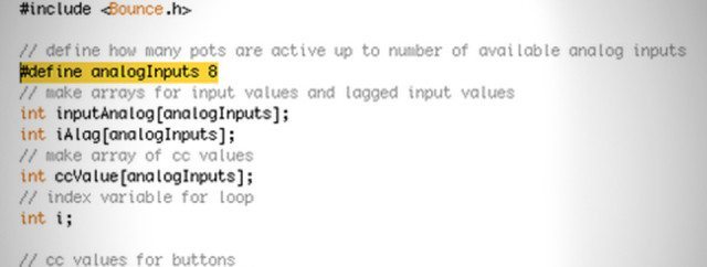
The Code#include
// define how many pots are active up to number of available analog inputs
#define analogInputs 8
// make arrays for input values and lagged input values
int inputAnalog[analogInputs];
int iAlag[analogInputs];
// make array of cc values
int ccValue[analogInputs];
// index variable for loop
int i;
// cc values for buttons
int cc_off = 0;
int cc_on = 65;
int cc_super = 127;
// map buttons to cc for button
int cc0 = 51;
int cc1 = 52;
int cc2 = 53;
int cc3 = 54;
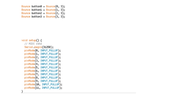
Bounce button0 = Bounce(0, 3);
Bounce button1 = Bounce(1, 3);
Bounce button2 = Bounce(2, 3);
Bounce button3 = Bounce(3, 3);
void setup() {
// MIDI rate
Serial.begin(31250);
pinMode(0, INPUT_PULLUP);
pinMode(1, INPUT_PULLUP);
pinMode(2, INPUT_PULLUP);
pinMode(3, INPUT_PULLUP);
pinMode(4, INPUT_PULLUP);
pinMode(5, INPUT_PULLUP);
pinMode(6, INPUT_PULLUP);
pinMode(7, INPUT_PULLUP);
pinMode(8, INPUT_PULLUP);
pinMode(9, INPUT_PULLUP);
pinMode(10, INPUT_PULLUP);
pinMode(11, INPUT_PULLUP);
}
void loop() {
// loop trough active inputs for knobs
for (i=0;i<analoginputs;i++){ // read current value at i-th input inputAnalog[i] = analogRead(i); // if magnitude of difference is 8 or more… if (abs(inputAnalog[i] – iAlag[i]) > 7){
// calc the CC value based on the raw value
ccValue[i] = inputAnalog[i]/8;
// send the MIDI
usbMIDI.sendControlChange(i, ccValue[i], 3);
// set raw reading to lagged array for next comparison
iAlag[i] = inputAnalog[i];
}
delay(5); // limits MIDI messages to reasonable number
}
// Push Button code
button0.update();
button1.update();
button2.update();
button3.update();
if (button0.fallingEdge())
{
usbMIDI.sendControlChange(cc0, cc_on, 3);
}
if (button1.fallingEdge())
{
usbMIDI.sendControlChange(cc1, cc_on, 3);
}
if (button2.fallingEdge())
{
usbMIDI.sendControlChange(cc2, cc_on, 3);
}
if (button3.fallingEdge())
{
usbMIDI.sendControlChange(cc3, cc_on, 3);
}
if (button0.risingEdge())
{
usbMIDI.sendControlChange(cc0, cc_off, 3);
}
if (button1.risingEdge())
{
usbMIDI.sendControlChange(cc1, cc_off, 3);
}
if (button2.risingEdge())
{
usbMIDI.sendControlChange(cc2, cc_off, 3);
}
if (button3.risingEdge())
{
usbMIDI.sendControlChange(cc3, cc_off, 3);
}
}
FINISHING TOUCHES
Before we test our creation, we first need to clean up flux residue with a paper towel and/or Q-tip (for hard to reach areas) and rubbing alcohol. This will remove any materials which could overtime corrode your board and connections.
After that dries it’s time to cover your connections that could potentially touch another and cause a short. You have a few options here: simply tape up any loose connections of bare wire that could touch another or even a metal component part; cover them with hot glue so nothing moves or touches at all; use heat shrink tubing (which doesn’t always fit perfectly); or try liquid electrical tape which comes in a rubber cement style bottle and brush on (which makes covering tight areas a little easier). *If using liquid tape please do so in a well ventilated area.
When the bare wires are covered, plug in your fully-soldered and connected circuit board. The LED should light up and not burn out! Boot up your DAW of choice and make sure you see the Teensy recognized as a MIDI device. Try mapping each component to your DAW and see if a MIDI signal is sent, once you’ve verified, you know you have achieved success!
Lastly, it’s time to close up your MIDI controller so it looks less like Frankenstein’s monster. You can use many things to mount the board in your enclosure but I recommend a generous glob of hot glue on the bottom. After it is mounted, plug in your adapter which is mounted to the enclosure, close the lid and seal it up.
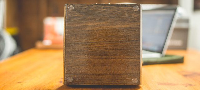
Final Product
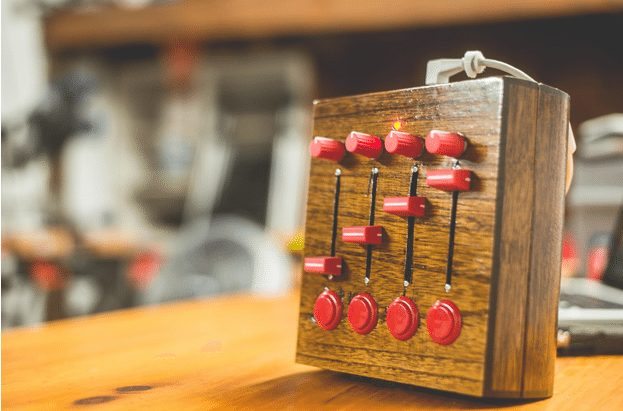
You are now the proud creator of your very first DIY MIDI Controller. Go show it off to the world, and be sure to post pictures of your MIDI controllers in the comments below or tag @DJTechTools on your preferred social network.
This DIY MIDI Controller is loosely a based on the DJ TechTools Midi Fighter 3D and DJTT Midi Fighter Twister.
Guide and design by Kyle Mohr
All video and editing by Alex Medvick
[…] https://djtechtools.com/2015/08/25/how-to-make-your-own-diy-midi-controller/ […]
Is it possible to use an Arduino board instead of a Teensy 2.0? If it is, can I still use the same wiring and soldering tutorial?
Yes, it certainly is. Soldering and wire schematic should line up just the same. You would just have to double check the code as the arduino pins may be numbered differently. Programming will stay the same, just if no faders or knobs, put 0 for the first line of analog inputs. Hope that helps!
[…] Learn how to make your own MIDI controller […]
[…] Learn how to make your own MIDI controller […]
[…] Via: DJTechTools, Check the original post here. […]
[…] Want more DIY projects like this for DJ gear? Check out our guide on building your own MIDI controller with a Teensy board. […]
Hey I’m using this video as a blueprint to build a similar controller at the moment. I’ve installed the arduino, teensduino and teensy loader software and set them all up correctly following all the steps in the video however i have a problem. when I try and upload the sketch to the board it says that it has uploaded but then nothing happens. It doesn’t come up with the ‘Reboot’ message or anything and also the ‘Program’ and ‘Reboot’ buttons are inactive and it won’t let me click them.
I then tried opening Ableton and it doesn’t recognise it as a MIDI controller. Also when I click the little button on the board I don’t think that it’s rebooting, all that it does is turn the LED light off on it.
Can anyone help? I can send you screenshots.
Matt
[…] MIDI controller for DJing, production, or visuals, but don’t have the money or time to make a DIY controller? In this article, we spotlight a project that DJTT friends Traxus Interactive have been working on […]
[…] MIDI controller for DJing, production, or visuals, but don’t have the money or time to make a DIY controller? In this article, we spotlight a project that DJTT friends Traxus Interactive have been working on […]
Wow…this will go a long way in enhancing not only productivity but also creativity
how do you code new buttons (digital) with this sketch?
Hey fellow inventors, musicians and engineers! I have been trying to get started with my own little build and as first thing I wanted to implement is Jog wheel based on rotary (grey) encoder and arduino. Basically reading the sensor works fine but I’m troubleshooting with my MIDI commands. At the moment I am sending serial command: 0xB1 0x23 0x3F (control change; controller 35; value 63) for one direction and 0xB1 0x23 0x41 (same thing with value 65) for the other direction. Hairless MIDI receives the signal correctly but Traktor does weird things: If I press play without any input it plays the track normally until I stop it but if I have the controller connected Play works for a fraction of second and stops automatically. If I try to use my controller I get movement only at one place: a little forward and then I can only move a little backward. In Traktor the device is mapped as Jog turn with relative setting(though with direct setting it enables me to move through the track but only in forward direction in response to turning encoder in any direction). I know that sending only one same value should move the track only a certain amount at the time but I should still be able to scroll through the track both directions. (similar signal is sent by Pioneer DDJ-SB2) So I am confused Any Ideas are welcome!
some question:
how many input is possible use with one midi controller ?
is possible connect many midi controller for make one bigger?
there are some problem about the latency time?
-Depends on the micro controller/circuit board you are using all have a different amount of max analog and digital inputs.
-In theory you could connect multiple buttons and knobs from various controllers, but you would have to cut all of their previous connections and wire them all to a new circuit board…I would advise against this.
-Close to zero latency, at-least with the Teensy and Arduino boards that I’ve used. If you were trying to daisy chain controllers or something of that sort, or use bluetooth, then you may run into some latency issues.
Hope that helps!
I just downloaded the sketch from this project. But when i try to upload the sketch to the teensy board i get an error that the functuion “usbMIDI” was not declared… do i need to add extra librairies? or to another action? I did not changed anything to the program just downloaded, opened it and try to upload it…
Thanks in advance
How can I add jogwheels? (Encoders)
Thanks KYLE MOHR,
Building a controller from scratch is simple but without a detailed guide like this, the reverse may be the case lol…
Thanks for the great tutorial! I am trying to build a simple version – just 6 faders – and am having issues. I used your code, after removing anything other than the lines for the faders (pots), and can get it to upload and even be recognized in my DAW (Pro Tools), however, when I set a fader to a control, the resolution is all out of whack, it almost seems like it’s using the range from 9k-10k ohm’s as 0-100 (or 0-127). If that doesn’t make sense, the fader doesn’t do anything until it is 90% up, and then goes to 100% in the 1/64″ travel at the end. Do you happen to have any suggestions to try to fix this? Thanks again for the inspiration for a cool project.
[…] other boutique products offer intense customizability under the hood, but at a much lower cost. DIY controllers that are custom built to spec can be surprisingly affordable, but require a lot of time investment […]
Hi
I have built a couple of MIDI controllers using Arduino Uno but I am about to start making a Midi controller with Teensy 2.0 what I need to know is how many buttons can I add? I am planning on adding 16 LED arcade buttons. How many digital inputs dose teensy 2.0 have? Please help as I dont want to cut out the enclosure wrong and have to start again. Thank you.
Teensy 2.0 has 25 I/O and 12 Analog. If you use any knobs or sliders you won’t have enough for the 16 arcade buttons, but if just buttons you will be perfectly fine!
I ended up getting a 16 button controller to work and will post a photo soon. I am now trying to build another controller with 16 petentiometers using a teensy 2.0 with a: 74HC4051 8 Channel Mux Analog Multiplexer Demultiplexer Module for Raspberry Pi, the only problem I have is I dont understand how to implement it in the code? Please help. Thanks
Ah, that sounds awesome. Would be glad to help. I would remove all of the code for the buttons, and at the top change the analog number to 16. As for implementing the Pi, I am unsure as I haven’t done much with those except PiCade, which lets you play retro video games off a Pi. I would definitely ask in the DJTT forums and even over at Adafruit as they specialize in this stuff.
Cheers that multiplexer I mentioned can be used with teensy 2.0 according to this blog I was reading. Hope I get it going.
[…] du scratch, erreur de manipulation d’un certain Grand Wizard Theodore, jusqu’à la création de contrôleurs MIDI utilisant des boutons de bornes d’arcades, et autres éléments de récupération, la […]
Great article. I posted here yesterday but something must have gone wrong.
I built a 5 button setup to control my video streaming software, vMix. It works great but I was wondering how I would use this midi program to get the tally light signals to turn the leds on in my buttons? I am a total novice to programing for midi, so if anyone has some code examples it would be a huge help.
Thanks.
What if I wanted more potentiometers? Like, lets say 8? And more buttons for stuff like what a Launchpad does? Just wondering if the tutorial is more gears towards that specific layout, or if there is many differences in adding more.
@Tyler
You could technically have up to 12 buttons and 12 analog inputs such as pots or sliders… You just have to adjust the software to match what you are using.
This is something that I’ve been watching about since I found out about the original midi controller video in 2011. Finally have the fund and reason to take on this project. My main concern is how one would go upon having a toggle button/switch to go between different banks, fairly new to ableton as a whole. Thanks.
Hey there,
reading this super documentary, I’ve also made mine with aluminium and teck wood.
I know how to build physical things, but I am completely out with coding…
I tried to update your code, but with no success. Buttons aren’t responding at all, and faders are not giving correct informations…(in Live, going from =-50 to 0db, but never go upper or downer, plus the moving looks like some logarithmic curve thus the sliders are linear ones…)
If you’re up for some help, I don’t think this is something crazy, and you’ll save my last days!
By the way, here are pictures!
https://uploads.disquscdn.com/images/02253e160e45994544bef6f87bca748180c1cbac974d5bee86c6fa116276e503.jpg
https://uploads.disquscdn.com/images/2888d44491dfaf7a26580d452954535bf24bdd303aa70821289fcd4e0ff3eea9.jpg
[…] http://djtechtools.com/2015/08/25/how-to-make-your-own-diy-midi-controller/ […]
Awesome tutorial! I have all the parts I need, but I have a few questions!
First, is there a way to test and make sure it works before soldering everything? I modded the code for 20 buttons and I would like to make sure I did it properly!
More so, does any other part of the code beside the button code need to me modified to add more buttons?
I’m making this out of an old NES, i’ll post pics when I’m done! <3
That sounds pretty awesome! No, as long as you put your potentiometer/analog count to 0 at the top and then add buttons to the code as needed you should be fine. Fair warning, there’s not a ton of real estate inside the NES cartridge, so I hope you’re using the system shell instead! Can’t wait to see the final product. Keep us posted.
Thanks bunches Kyle, the code is done and I’m ready to start building!
It’s out of the shell, as you can see! I’ll post it here and in the forums when I’m done! <3
Nice!!!! This is going to be pretty amazing! I’m excited to see how this turns out.
I am too! However, could I ask you a quick code question?
I had to modify the code quite a bit to get 20 buttons on this, including the MIDI CC values in the code! However, I have a huge hunch that I didn’t set it properly!
Here’s the modified code that I have on my Teensy++: http://pastebin.com/zL2xKwTe
More so, when I open Ableton it says I have a constant MIDI signal going into it! I don’t have any buttons or pots connected yet, so this may be why, but is this another code issue?
Thank you bunches Kyle, I can’t tell you how much this article helps!
Sorry for the delay. Hopefully you got this thing up and running. Would love to see the final product. From the code it looks like the pinup section only goes to 11. And the only other thing I would think of you be making sure you had your buttons soldered to the right pins.
Here’s my latest incarnation!!!!
Thanks for the Insipiration….
Great job!! This looks amazing. What does the screen do? Show values or mirror the DAW?
Thanks!!!, Still work-in-progress… It’s a touch screen so endless possibilities… Right now its just wired to the pitch bend (Khaos pad like), but I’m working on the code to remap the faders, buttons ETC & maybe DAW info!!!!
Nice! I like it as a Kaoss pad feature. Send me a link for that, I’ve been meaning to mess with touch screens. Let me know how this turns out in the end. A demo video would be awesome.
Cool.. Will do!
Just a short video of the beast in action!! https://youtu.be/9oHjYrsy6xw
This is amazing! Great work.
Just a short video of my controller in action!!
https://youtu.be/9oHjYrsy6xw
Hey Kyle, Great article and video.
Thought I’d give this a try, but found myself stuck after the Teensy Programming. So it shows up as a midi device in Ableton and what not, except the midi indicator (In Ableton) stays on. None of the pots or buttons work. Any idea on what this could be?
Thanks
I’d make sure if they’re CCs and not notes assigned, you would need to use the learn function to assign them. The only other issue would be to make sure the code went properly to the board and that everything is soldered correctly. Hopefully you got this up and running!
Thanks for replying.
I eventually sorted it out. Just some loose solder joints.
Here it is:
https://uploads.disquscdn.com/images/d44bcadd03552b09df735bb57ae38e42fc8c05cea5f778562d264661c51ae484.jpg
Looks awesome! Great work.
Can you provide a schematic if you had 8 arcade buttons, 4 potentiometers, and 4 sliders? I’m a little confused and I need a little more information using a schematic to show which cable goes where, and what cable is in use for what.
Also, I know I’m really, really late to post here, but I really need some help. This post is really amazing but I’m currently in the process of soldering and I’m stuck at a certain point. Please get back to me if you can, Kyle.
I’m a little late in response but hopefully you got this up and running. pots and sliders are all on the analog side and buttons are on the digital side of the board. The little postcard that comes with the Teensy board should show you a small guide on what pins are what. On how to wire the pots, this is a different project but a great layout for wiring pots: https://learn.adafruit.com/mini-untztrument-3d-printed-midi-controller/circuit-diagram
[…] ??????DJ Techtools […]
Is it possible to program the buttons send a MIDI note on message when pressed and a MIDI note off message when released?
Yes, you can just remove the button code and replace with what pin should trigger what midi note.
Thank you! This was really useful, i always wanted to make a MIDI controller, and after reading this I know how to.
Hello
I would like to make my own midi, but unfortunately i am living outside of america
So I only have Arduino. Is it okay to replace teensy as aeduino?
Yes, Arduino is just as good, just a lot larger and a little bit harder to program midi on.
how can i go to user 1 mode with drum racks?
Program the buttons for midi notes (instead of CCs) to match up with the midi notes of the drum rack.
hi guys! thank you for the very good project, I make one similar but i have problem whit my potentiometer, they make me noise and its not precise, they are not stable , they move constantly : / you can help me understand why ? I have already tried to filter the signal with a condenser from 0’01nf but not working.
Hi, does this code works with Genuino UNO as well?
Not sure, worth a try, but it is lined up for the Teensy 2.0 pins, so you may have to alter the code a little.
is the Micro usb to usb b female necessary? , can I also use an micro usb to usb a?
no adapter necessary, you can pug straight into the board if needed.
What would be a good material for wood?
Oak, pine, something on the softer side so easy to drill but hard enough to make a strong, durable controller. Any wood should work just fine. Plywood might be too rugged.
Excellent article!!!
Just one simple question… Is it possible to use led-illuminated arcade buttons instead? Should I consider anything else? I’m using Teensy 3.2 to add up to 21 inputs. Thanks a ton!
Shouldn’t be a problem. Just would have to research what resistors would work best with those and be careful wiring them up.
[…] How To Make Your Own DIY MIDI Controller – DJ TechTools – Learn how to design, build, and program your own DIY MIDI controller based around Teensy and Arduino for less than $100! […]
[…] Want more DIY projects like this for DJ gear? Check out our guide on building your own MIDI controller with a Teensy board. […]
[…] Want more DIY projects like this for DJ gear? Check out our guide on building your own MIDI controller with a Teensy board. […]
[…] We’ve always enjoyed a touch of dark wood on DJ gear – like the MP2014 – as long as it’s done right. In addition to a few manufacturers jumping onboard the wood trend, we’ve seen a number of DIY projects like the above pictured X1 stand, or the case that Kyle Mohr used in last year’s DIY MIDI controller guide. […]
Could I make one of these similar to a mini untz or midi fighter (layout wise), but with Teensy instead of a Trellis and Arduino?
Absolutely! Just swap out the MIDI CCs for Midi notes in the code.
I know this sounds a bit nooby but can someone breakdown how to code the controller if I was using 19 buttons and 3 faders and 5 potentiometers. Thanks
In short, you would change the analog number at the top to 8 to cover faders and pots, then adjust the button code to 0,18 and so on.
@disqus_SkWrr9Ijq6:disqus great video / article! But I have just 1 question for ya… I’m about to start building my own, and I want 16 buttons and 1 fader, can I achieve this with a Teensy 3.0? Or do I need something that accepts more inputs? If so , think you could help a brother out and point him in the right direction? Thanks in advanced!
I would say a Teensy ++ would give you more than enough, but the 3.0 should be fine as you only have 1 fader,
@disqus_SkWrr9Ijq6:disqus , great video / article! But I have just 1 question for ya… I’m about to start building my own, and I want 16 buttons and 1 fader, can I achieve this with a Teensy 3.0? Or do I need something that accepts more inputs? If so , think you could help a brother out and point him in the right direction? Thanks in advanced!
[…] MIDI Controller Price: $200+ (see our supply list)Ideal For: DJs who need a custom control surfaceWhy It’s A Good Gift: The best gifts are […]
[…] MIDI Controller Price: $200+ (see our supply list)Ideal For: DJs who need a custom control surfaceWhy It’s A Good Gift: The best gifts are […]
[…] Draw it out in Lemur and make it a reality. Trust us, this is much cheaper and less hassle than building your own MIDI controller – although we do have a new great tutorial on that as […]
[…] Draw it out in Lemur and make it a reality. Trust us, this is much cheaper and less hassle than building your own MIDI controller – although we do have a new great tutorial on that as […]
[…] Draw it out in Lemur and make it a reality. Trust us, this is much cheaper and less hassle than building your own MIDI controller – although we do have a new great tutorial on that as […]
[…] Draw it out in Lemur and make it a reality. Trust us, this is much cheaper and less hassle than building your own MIDI controller – although we do have a new great tutorial on that as […]
[…] Draw it out in Lemur and make it a reality. Trust us, this is much cheaper and less hassle than building your own MIDI controller – although we do have a new great tutorial on that as […]
great tutorial though the code is bugged, when connecting my teensy to ableton, ableton crashes and will not re-open until my pc is restarted. im assuming this has something to do with a missing analog write function so if you choose output for the teensy in ableton it builds up data going to the pots until the program cant handle it and crashes.
I have a question. What if you want to put some kind of display in your controller? How would it be progtamed? Becouse teensyduino doesn’t have a midi+display option.
thanks
how do I calibrate the faders?
I have a problem with my midi controller, the buttons and potmeters are not working, when I link something in fl studio than the knob in fl studio goes crasy, when I remove al the code for the potmeters the buttons does work.
I have two potmeters and two buttons ,my potmeters are on pin 23 and 22,
here’s a list of what I tried:
– Use only 1 potmeter
– Use only 2 potmeters
– swap the ground and power wire
– tried multiple potmeters
– Use other pins on the teensy
– tried changing the code in multiple ways
The code for 1 potmeter:
#include
// define how many pots are active up to number of available analog inputs
#define analogInputs 1
// make arrays for input values and lagged input values
int inputAnalog[analogInputs];
int iAlag[analogInputs];
// make array of cc values
int ccValue[analogInputs];
// index variable for loop
int i;
void setup() {
// MIDI rate
Serial.begin(31250);
}
void loop() {
// loop trough active inputs for knobs
for (i=0;i 7){
// calc the CC value based on the raw value
ccValue[i] = inputAnalog[i]/8;
// send the MIDI
usbMIDI.sendControlChange(i, ccValue[i], 3);
// set raw reading to lagged array for next comparison
iAlag[i] = inputAnalog[i];
}
delay(5); // limits MIDI messages to reasonable number
}
}
I would appreciate your help, thanks
I have a problem in the code, it gives me the th error: ‘ccValue’ has a previous declaration as ‘int ccValue [59]’ I have googled it but I can’t find the solution, I have 2 potmeters and two buttons connected here is the code:
#include
// define how many pots are active up to number of available analog inputs
#define analogInputs 2
// make arrays for input values and lagged input values
int inputAnalog[22];
int inputAnalog[23];
int iAlag[22];
int iAlag[23];
// make array of cc values
int ccValue[59];
int ccValue[50];
// index variable for loop
int i;
// cc values for buttons
int cc_off = 0;
int cc_on = 65;
int cc_super = 127;
// map buttons to cc for button
int cc0 = 51;
int cc1 = 52;
Bounce button0 = Bounce(0, 1);
Bounce button1 = Bounce(1, 1);
void setup() {
// MIDI rate
Serial.begin(31250);
pinMode(0, INPUT_PULLUP);
pinMode(1, INPUT_PULLUP);
}
void loop() {
// loop trough active inputs for knobs
for (i=0;i 7){
// calc the CC value based on the raw value
ccValue[i] = inputAnalog[i]/8;
// send the MIDI
usbMIDI.sendControlChange(i, ccValue[i], 3);
// set raw reading to lagged array for next comparison
iAlag[i] = inputAnalog[i];
}
delay(5); // limits MIDI messages to reasonable number
}
// Push Button code
button0.update();
button1.update();
if (button0.fallingEdge())
{
usbMIDI.sendControlChange(cc0, cc_on, 3);
}
if (button1.fallingEdge())
{
usbMIDI.sendControlChange(cc1, cc_on, 3);
}
if (button0.risingEdge())
{
usbMIDI.sendControlChange(cc0, cc_off, 3);
}
if (button1.risingEdge())
{
usbMIDI.sendControlChange(cc1, cc_off, 3);
}
}
what do I have to put in the code in the top with the analog things
where do you have to put the analog input numbers in the code?
can I use a teensy 3.2, how do I connect the power on the teensy 3.2?
@bertplays:disqus yes, you can!
Any Teensy board should work.
The power should still be in the same spot on any of the boards (1st pin on the right or left side by the USB port), just make sure to use the pin labeled “VCC”.
I have a teensy 3.2 and there is no pin labeled VCC, there are two pins labeled: 3.3V and there is the first pin on the right of the usb that is labeled as vin(3.6 to 6.0 volts), you can google the board if you want
Is +5 v for the power necessary, can I also use 3.6 V?
hi could anyone help me with the code please ?
i have added 2 more arcade buttons and a arcade joystick so basically 6 more buttons
and have tried to alter the code but dont realy have a clue what im doing
so when i come to program the teensy 2.0 i get error In function ‘void loop()’
DJTT_DIY_MIDI:106: error: ‘cc4’ was not declared in this scope
and so on for the other entries i have added .
Hey, I’ve got a question: Does the whole project also work well with the teensy 3.1 (and is Teensy 3.1 the latest version at all) ?
It definitely should. The 3.1 is the newest board, I just used the 2.0 because its cheaper and sufficed for my project. You may just have to alter the code a little to line up with the pins you are using on the board, otherwise it should essentially be the same.
If I used a full arduino board and wanted to add a touchscreen for x/y purposes but would like to keep the knobs, faders, buttons, how would you work it into the circuitry?
if i wanted to add an x/y screen to my controller, how would i go about programming that and adding it to the teensy?
A quick tip for those of you planning to use arcade buttons with your project: https://youtu.be/uH7P_FbQUlw
Thanks Kyle, awesome article, very inspirational. Also of all the recent guest contributors this is the best. Well done. Just need to decide on a design…..
Thanks Nik! Much appreciated. Be sure to post your project here! We’d love to see what cool MIDI device you create.
Thanks for sharing! But I have an Arduino UNO board, How to make it as a MIDI device?
I just mad a controller about a month or two ago. Its still not completely finished because of sold out parts but this is what i made. I think its pretty obvious its oriented on the Traktor F1 but with the 30mm Arcade Buttons its much bigger and also is capable of better finger drumming. Its fun to use and works with an arduino. Still have some Problems with the Lighting of the buttons. Something with the currency of the in/outputs. But as you see it looks pretty neat and can be Powered by USB only or by an aditional powerchord. I made this due to an educational project. This article comes a little bit later, i oriented on the earlier article and used an instruction on instructables. The aluminiumplate at the top is CNC cut and the case is made by hand and glued together. I think about getting some chroma caps for this controller, it would look awesome with them on 🙂
By the way its an Arduinomega because it has more I/Os than many other hardware or the uno.
That is one sexy controller, colour me impressed,and once that crossfader is installed that’s a f1 killer for sure.
Did you solve the led issue? I’m planning to use led arcade buttons with a Teensy 3.2 but nit sure if it would be a problem. Thanks!
A little late for a reply maybe but no, I didn’t solve it yet. I threw them out of the project. My concept for the lighting was bad and the room in the controller wasn’t enougth even though it’s pretty big. I may add some simple white lighting in future though. But nothing adressable. How did your project go?
Great work! This is so Pro!
nice write up, quick Q.. the resistors isnt needed if were not using the LED correct? i wanna do one with 12 rotary encoders like these.. http://au.mouser.com/ProductDetail/Bourns/PEL12S-2024S-N3024/?qs=sGAEpiMZZMsWp46O%252bq11WTU2mLe3dQ9doksdYy18gMQ%3d
anything else i should know?
Correct. No resistor needed if you aren’t using LEDs. If you plan to use a potentiometer with built-in LEDs like the one in link, I would just double check to see if it has a built-in resistor or requires one. Should have a data sheet on the page for reference, but Mouser customer service is usually pretty helpful too.
Hello, who can draw a diagram of the video controller and articles ???
Thanks guys for a great guide. I’ve had a Teensy 2++ for a minute now, waiting for me to finish some other projects. I want to make a midi controller that (I hope to be) uber-simple. I want to make a five button (actually guitar pedal stomp switch) midi controller for a very specific action during my Ableton sets- to activate and deactivate effects. I can handle making the sturdy enclosure and wiring the stomp switches, but I want to make sure that I can use the method you’ve got here to make it a bonefide MIDI controller that should work while I use my traditional desktop controller (the Livid CNTRL:R.) Seems like it should be no big deal… I’d just have to make it, and map it manually, with the effect on/off, one per switch…. right? I’m not being presumptive or ultra stupid here, am I?
Thanks Pete! Not a stupid question at all. You’re correct. Just make sure when you setup the board in the arduino app to select MIDI and then it should come up in ableton just like any other MIDI controller would, but will probably say teensy MIDI. When mapping just click what you want to map and click the button you wish to use. If you’re using the same code from this project all you should have to do is add code for 1 button, mark it 4 of 4, and change the analog inputs section at the top to 0.
Nice walkthrough! For the people scared of programming and electronics, I’m building MIDI platform, kinda like Livid Brain, but open-sourced. Still looking for suggestions etc. I really want it to be community driven. It’s going to be finished in few months – basically the only thing missing is GUI configuration utility, but if you know your way around MIDI System Exclusive you can use it right now. You can check it out in the forums:
http://forum.djtechtools.com/showthread.php?t=83148
That’s awesome! Thanks for sharing.
[…] post How To Make Your Own DIY MIDI Controller appeared first on DJ […]
Im thinking of buing teensy 3.1 with pins. Specification says it has 21 analog inputs. So 21 potentiometers then ? But this drawing shows that 7 analogs are in same pins. Ho do you connect 2 jumper wires to 1 pin?
https://forum.pjrc.com/attachment.php?attachmentid=1793&d=1396800490
yeah, a mix of 21 pots or faders! The additional analog pins are actually the metal pads on the bottom, and the little pins/holes in the center of the board that are labeled.
we know it’s easier to get a brain or brain jr. kit from livid right, or am I missing something?
Oh it is definitely easier to go that route, just starting at $45 and up for the brain sets you back a bit. The teensy runs for $20, so I’ve definitely made a smaller controller for only say $30-$50 total. If you have the extra dough and want to save a ton of time the brain and brain jr. are indeed great alternatives! Good suggestion.
Also, I love the collection of random stuff in the top photo that has been turned into midi controllers! so much creativity!
Thanks! Those were the first batch of controllers I made.
Man, I wanted to do this article a while back, but this is far better than anything I would have done. Excellent article, this is exactly what got me into DJTT back in the day, this is like a return to roots!
Anyway for those Interested, this is the code I wrote for my custom controller, its for the Arduino Mega 2560, connected to the Mayhew Labs Mux Sheild (original) (uses cd74hc406 multiplexers, any 16 channel 4067 will work)
The code is very basic and unrefined, but easy to understand with instructions posted throughout it, its for my controller, so trim it back and adjust it to suit yours. This is on you though, I will not write the code for you, you should have a basic knowledge and an ability to deduce how to set up the code for your application. Its not that difficult really, just READ the pointers throughout the code.
Download Here:
Basic Arduino Midi Code, Debounced buttons, Leds and Pots/Faders
http://jmp.sh/v/7lnoASiJdmQlPStm8pmX
Thanks Noxxi!
Awesome of you to share the code you wrote. This is exactly what its about, sharing our knowledge to make a better resource center and DJ community.
Thanks dude, love the variety of controllers you’ve made, I’m just about to google you for more awesomeness!
Your right, though. I spent a good few years trawling the internet looking at pictures and sifting through code examples before I understood enough to give it a bash myself. It can be very off putting, especially for someone with limited time or someone who doesn’t think they are smart enough to learn it (even though they probably are). I for one would love to see more home made creations, especially awesome looking ones.
So here’s mine, I couldn’t resist showing it off! 😀 theres TONS more build pics as well, I was totally intending to make a build log for either here or instructables or something.
I’d also just like to say, for anyone else reading this, the Arduino forum is a GREAT place to get help with your midi controller projects, they answer quickly as well, but you MUST treat them with respect, and recognize that they won’t help anyone who isn’t willing to at least try to figure it out themselves, in other words, use them as a last resort, but they are amazing, A huge shout out to Grumpy Mike on the forum too for all his help. ( i doubt he’ll read this though, but you know… 🙂
Thanks dude, love the variety of controllers you’ve made, I’m just about to google you for more awesomeness!
Your
right, though. I spent a good few years trawling the internet looking
at pictures and sifting through code examples before I understood enough
to give it a bash myself. It can be very off putting, especially for
someone with limited time or someone who doesn’t think they are smart
enough to learn it (even though they probably are). I for one would love
to see more home made creations, especially awesome looking ones.
So
here’s mine, I couldn’t resist showing it off! 😀 theres TONS more
build pics as well, I was totally intending to make a build log for
either here or instructables or something.
I’d also just like to
say, for anyone else reading this, the Arduino forum is a GREAT place to
get help with your midi controller projects, they answer quickly as
well, but you MUST treat them with respect, and recognize that they
won’t help anyone who isn’t willing to at least try to figure it out
themselves, in other words, use them as a last resort, but they are
amazing, A huge shout out to Grumpy Mike on the forum too for all his
help. ( i doubt he’ll read this though, but you know… 🙂 😀
Great tip on the arduino forum! And Dude… That controller is AMAZING! Must have taken forever to put together but it looks so pro! Great work. Here’s my most recent before this project.
Thats so awesome, I love the fader cap, it looks like a little pacman ghost! Plus the added bonus of being able to quickly open it for upgrades is pretty cool as well. I think my smaller buttons are the exact same as the black ones on yours, kind of like arcade buttons but a fair bit stiffer?
Aw dude, yeah it took me months, several all nighters, trying to figure out the code, how to wire it as neatly as possible and reliably as possible too, the most stressful part was trying to solder the wires to the pin headers, i ended up using a bit of veroboard, but still its not ideal. I really should have got some sort of wire crimps or something. Also the acrylic was annoying, if the hole cutter snags even a tiny bit it shatters, which always happened when it was nearly finished.
And the wood came off an old pallet that was lying around, sanded it like mad and used some brown boot polish on it, which gives a surprisingly nice feeling and looking finish, as well as being super easy to apply.
Thanks. It is a 3D Printed pacman ghost fader cap! And yes, mini arcade buttons are the same, they do require a little more push though. Haven’t worked with acrylic yet, and after hearing that, not sure if I want to! ha. The pallet wood looks awesome! Definitely trying that and boot polish beats stain + poly that takes days to dry. Great inspiration man.
Aah, well a successful design then! I seen some of your more colourful designs, they look pretty sweet, but if it were my money, I’d go with the ones that are designed like that white one, they look the most pro. hell you could probably sell them!
Aw yeah dude, the acrylic was a nightmare, I still cracked my final top plate, but it was just between 2 arcade buttons, so it wasn’t the end of the world, I decided to just live with it, next time id probably use aluminium and cover it with fablon. Fablon is awesome btw, I’ve done my Push with yellow carbon fibre fablon, the cool thing is the fablon is easy to swap out for any colour or design you want. I regularly do my lapop in different colours with it. love it!
Thanks! Aluminium would be sweet. Definitely post a few pics of that once you finish. And awesome about the Fablon! I think I may have to pick up some this weekend! Tons of great advice. Thanks Noxxi.
What board did you use to get all those buttons? You can only have 12 on the Teensy.
I used an arduino mega and a mayhew labs mux sheild (arduino mega wont show up as a midi device unless you flash the hiduino firmware, requires a isp programmer)
the mux sheild is a simple board with three 16 channel multiplexers on it, the way it works, is you use 4 pins to select the multiplexer channel (in binary, so the pins are 1,2,4,8. adding together combinations of those binary pins gives you 0-15 ie 16. so the 1 pin and the 8 pin would give you channel 9 and so on)
using this method, you can have 16 ins OR outs of any type (no mix and match on 1 multiplexer) using just 1 pin, plus the 4 control pins. the beauty of them is that say you use 3 multiplexers, you still only need 4 control pins as they can share them, and you can get 3 different 16 channel inputs or outputs, so for 48 ins and outs your using only 7 pins.
hope that was nice and clear, its a lot to take in if your just starting. 🙂
Good job Kyle on walking trough the entire process and Alex for putting everything together in the video! Really enjoyed the tame watching it – cool stuff!
Here is my first and only DIY controller for Traktor 😉
[img]http://i.imgur.com/mEIxEs2.jpg[/img]
Still works!
Thanks Stewe! Appreciate it.
That’s a pretty sweet MF clone!
What board did you use?
Oh, it’s nothing fancy really. I used a cheap USB gamepad and then converted signals from HID to MIDI with the freeware software called Rejoice. It was meant to control the Instant Gratification effects with the buttons and the free space was dedicated for four rotary pots but I never actually made the to work properly out of the joystick analogs… I planned to instal one of Livid Brain Jr’s to make pots functional.
AH. Nice! I’ve seen that done before with the gamepad, I think the knobs would be a great addition to this!
Sorry but i’m not an expert but can you give me the code for 16 arcade buttons ? Thanks
OMG YES!!! Been waiting for an article like this!!
I usually play a lot of fighting games on Steam and GGPO. Because of that, I own a Madcatz USB Fighting Stick. Anyone knows how use it as a midi controller?
What kind of hacks can I do with it?
If you’re using a PC you could use “Joy to Key” or for mac there is “GamePad Companion”. You just push a button or move a control then assign what keyboard key you want it to trigger. You would just have to make sure the keyboard as MIDI function is turned on in your DAW.
wooow, many thanks bro 😀
will try this when arrive at home
[…] More: DJ TECH TOOLS Article By: KYLE MOHR at DJ Tech […]
Nice Work really… I always said that Arduino is a powerful tool.
this controller will be used to TRAKTOR?
Thanks! It can be used with anything that accepts MIDI over usb. Ableton, Traktor, Serato, iOS apps, etc. But yes, it would ideally work as a 4 deck “mini-mixer” for Traktor.
All I can say is…respect. Great article. Thanks. Let’s try.
[…] post How To Make Your Own DIY MIDI Controller appeared first on DJ […]
Thank you DJTT. This is exactly what I requested a few months back when you asked for article ideas. Great job!
My issue is always cost. Every design that I would want, always ends up costing so much more that buying a manufactured version. Want a 8×8 arcade layout? Might as well just buy a launchpad or almost buy 4 midi fighters, between the cost of say a Livid Brain and the buttons, you’re buying an Ableton Push. For more specific functionality though (like the illustrated) it does make some sense.
Agreed, DIY doesn’t always mean cheap. Sometimes factoring time it takes to build and all of the materials you’ll need it doesn’t add up and you could buy pre-made for the same price. The teensy boards tend to be the cheapest and smallest boards I’ve found vs a brain.
Yeah, there are definitely places for DIY though, While manufactured, I actually look at the MF devices as DIY ‘conceptually’, yeah I have other 4×4 devices (or had), but each one excels at a certain thing and that is where I think the money and time are worth it. Something like the faders above will work in both Traktor and Serato and Rekordbox. I personally want to make one just because I’m an elec engineer who doesn’t get to do engineering at work (so is life sometimes) so it would almost be ‘fun’, its just the cost of that fun hehe.
Especially since the three projects I want to try are going to be pricey – either a 16×4 grid (remix deck or Ableton drum interface) with arcade buttons, a large jog wheel that moves like vinyl (Sorry, S8 was a no go for me strictly for that reason), or something for making Thor (Reason) a tangible synth. In Ableton, the Push does a good job with device controls, but Reason has nothing like that, Panaroma Nektar or whatever is the closest thing…but real knobs are the way synths should be.
Yeah, half of it is the fun of building something truly unique and custom + being able to tell people you made it yourself! All 3 projects sound pretty awesome, would love to see the final result!
[…] post How To Make Your Own DIY MIDI Controller appeared first on DJ […]
THIS ARTICLE! RES-PECT.
DJtechtools i salute you on an exellent article and video. and for Kyle Mohr, really sweet controller dude. i like to built small analog lo fi synths and effects and ive been really interested in getting into controller building but i haven’t yet. i already have an old arduino and a teensy2++, just can never decide on the design of it…. haha.
Realy clean work, and thanks for showing me the potential of cheap softwood boxes… enclosures have always been my weak point!
it’s just what we were talking about a few weeks ago!!! props to DJTT for this amazing article!
Thanks!! Enclosures are the fun part for me. I got into this because I wanted to turn an NES cartridge into a controller. As for arduino vs teensy both are great but I found teensy easier to program as MIDI.
yeah teensy can handle midi over usb waaay better than arduino!
Hi Kyle, can you enhance on why teensy is easier to program as MIDI please? Is it just down to faster processor power? Thought that the only main difference was size? Many thanks, Nik
Hey Nik,
Yes, with arduino you have to do a little song and dance to trick your arduino into thinking its a native USB MIDI device, see here: https://learn.adafruit.com/untztrument-trellis-midi-instrument/code. The teensy on the other hand is only the click of a drop down menu to make a MIDI device, no 10 second rush to fool it.
Thanks mate
Thanks, realised I never replied months ago sorry, cheers, Nik
Hey DJTT, do you have to stick to that design/configuration of faders, buttons and knobs? Or can you for example just have faders, or just buttons? And also can you build the case a different shape to the one in the video?
You can make any configuration you want and any case you want with this – you’ll just have to modify the code slightly. See Step 4 in the Programming section.
Has anybody any experience with rotary encoders in such projects ?
Like KY-040 for example? I’d need code and wiring diagram please. I’m making a rise stand/midi controller for AKAI AMX with cue point triggers and rotary encoders for loops.
Pictures soon 🙂
Did you ever end up making this? I’m looking to make an AKAI AMX stand + pitch fader + cue buttons.
Here https://serato.com/latest/blog/18504/diy-custom-akai-pro-amx-stand?utm_source=facebook&utm_medium=social&utm_campaign=diy%20custom%20amx%20
This is amaze-balls.
Thanks Graham!
Before you drill the holes in the wood, place what will be the topside of the board against another piece of wood. Think of it like a two piece wood sandwich with the topside of your controller board in the middle. Drill from the backside of your good wood. That way the drill bit won’t break off the edges of the holes leaving that chipped ghetto look.
Great pro tip!
I make a lot of my own studio furniture and cases. 🙂
Tarekith you always amaze…
ITK blades also give a more finished edge than regular rip blades. Did millwork for a few years then ran a dual stage rip and crosscut Holzma.
Agreed, great tip! I’ve only done that with plastic. Will be sure to use on wood as well from now on.
Didn’t mean to imply your case looked ghetto either, that’s just what my old shop teacher called it. 🙂
haha, none taken. I think I even say in the video “this will always look crappy.” Its a great tip! I always banked on the washers and button rings to cover up the ugliness.
WOW, PRO TIP HERE haha
Also worth looking into: Adobe Photoshop CC has an option to export 3D files to Shapeways (a service which will 3D print objects and mail them right to you.) Its really not that hard or expensive. If you own/know Photoshop (or someone who does) this is a really attractive option for many reasons. https://helpx.adobe.com/photoshop/how-to/photoshop-print-3d.html
It was a great video, but i feel like you left out a lot of options, there are many cool things that can be used for midi controllers such as the omni boards and the brains from livid instruments, the breakout boards and rubber pads from sparkfun electronics and the akai rubber pads which are available all over the place. I think the video would of been better if it showed and explained more options, rather then just showing you how to build one specific midi controller.
Well why don’t you make a video and show us all how to do it.
States takes 2-3 weeks (this will, however, give you plenty of time to get your enclosure ready and board programmed). But, to make things easier I’ve provided many links for Amazon and US retailers.
I don’t disagree that having access to hot-to info on other options would be good but the author gave us a bit of _GOLD_. He gave us one full and relatively complete example. He showed us every step in the process. Never underestimate the worth of a complete example to the n00by controller builders out here.
OTOH, I agree with Jason (who also replied) — show us some examples of what you’re talking about. The entire n00b controller builder community would benefit from what you can show us…
If we’d all follow the old hippie philosophy of “each one teach one” the DJ world would be a much better place. (for instance: http://djtechtools.com/2010/12/12/usb-power-problems-we-can-fix-them/ — my money where my mouth is…)
I haven’t encountered the USB problem in your article yet but it was a great read and something I wouldn’t have thought about until it happened so thanks Dennis
Unfortunately im a student with no time to write a full article on creating MIDI controllers however to any newbie reading this, the best way to learn is through forums. You can find some helpful threads in the audrino, Livid instruments and djtt forums, which are active and have many people of expertise there that are willing to help. Also, google is your best friend, make sure you search before you ask. for components i recommend sparkfun electronics and adafruit (and ofcourse the awesome djtt chroma caps). For the brains check out audrino and livid instruments.
Agreed, there are a ton of other great boards and components to build endless amounts of custom controllers. Great suggestion! Maybe I will do a follow up video to discuss all of the other options out there. We just wanted to scratch the surface with this one first and go from start to finish with a basic idea to get people started on the cheap.
Completely understandable 🙂 and im sure that when i was starting to look into making midi controllers this video would of been a ton of help!