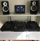
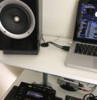
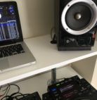
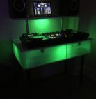
A dedicated DJ booth is one of the best things you can have to make sure you regularly practice at home. Today we’re sharing a DIY instructional guide on how to build a DJ booth that has integrated RGB lighting inside of it, all for less than $300. Keep reading for the full instructions from guest contributor Brian Bentley!
DIY: Light Box DJ Booth
Recently, I moved into a new apartment and the old IKEA DJ booth I had constructed wouldn’t fit. After seven years and three moves, it was becoming less sturdy and pretty scratched up. I gave it away on Craigslist and started dreaming of a new one. After searching for DIY and professionally built booths, I decided to build one because I wanted:
- The exact right size to fit space in my room
- To be able to use CDJs or turntables (and have storage for what wasn’t being used)
- A permanent shelf for laptop/speakers
- A place on the booth to store turntables/CDJs when not in use, hide wiring and SL3 box
- Something with a unique look
After contemplating an initial boxy, solid wood design, I decided it would be too heavy and boring looking. In trying to reduce the weight, I added four short metal legs inside the enclosed area so the side panels wouldn’t have to be structural. With a solid color plastic in mind, I started searching online for something I could use as side panels.
Inspired by another DIY booth with RGB accent lighting, I had the idea to turn the enclosed space into a light box. So I started looking for translucent white panel and found a local plastics place. They carried transparent white, cast acrylic that would do just what I wanted.
Below, is a complete guide on how I built this light box DJ booth – including some pro tips and changes to consider when building this DJ booth for yourself. Click the drop downs below to view what you’ll need to build this project!
Materials ListStep-By-Step Construction Guide
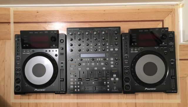
Step 1: Measure!
- The dimensions I needed (based on the space in my house) were 43.0” wide by 23.75” deep.
- To figure out an ergonomic height, I measured from the floor to my elbow, with my arms bent 90° (as if I was DJing). This was 38.5”, which will be the height of the CDJ platters.
- I determined the speaker and laptop shelf needed to be 43.0” wide by 12.75” deep, based on their respective sizes.
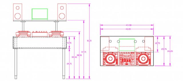
Step 2: Parts & Design
- I first tried to source all parts from IKEA, but had issued finding exactly what I needed. Additionally, a lot of IKEA tabletops are a paper honeycomb construction, which doesn’t work well for cutting or drilling. They also scratch easily. My work desk is a melamine tabletop, so I decided to go with that. Home Depot online showed that my local store had a bunch of melamine boards, 0.75” thick, in white (it does come in other colors, but might take some hunting). One 4’ x 8’ melamine board would yield all three pieces needed, and Home Depot cut them for free.
- On IKEA’s website, Olov legs seemed to have adjustable min/max height range needed, based on the 38.5” CDJ height I measured (worth noting, these legs ended up needing more support. I recommend finding something more structurally sound).
- For the legs inside of the light box, Godmorgan legs would work well. They have a bracket on one end used to attach it to whatever and the other end is an adjustable foot. My plan: remove the adjustable foot (basically a bolt with a plastic foot) and secure the leg by running an actual bolt through it.
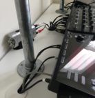
- For hide wires on the the laptop/speaker shelf, I planned on having hollow mounts with galvanized pipe to run the wires through. I wasn’t sure how tall to make the shelf – aside from tall enough that it didn’t interfere with DJing. After looking at lengths readily available, I felt 12.0” would suffice.
- I decided to have my local plastics place cut-to-size the side panels. (Tip: You can save money cutting these yourself, but plexiglass cracks easy if not cut correctly.)
- Based on all these parts, I sketched up the project in AutoCAD (image above), and then went out and purchased all the materials.
Step 3: Construction
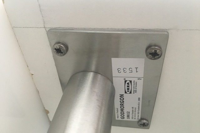
- Attaching the Godmorgan legs to form the light box was the first step. I chose which of the two 43”x12.75” melamine boards would be top and bottom.
- On the underside of the top board, I measured and marked a pencil line 0.75” from the edge of all four sides of the melamine board. I installed three of the four Godmorgan legs in the corners of the 0.75” perimeter with the supplied screws. Before attaching the fourth leg, I unscrewed the leg bracket and used it to mark where I would need to drill a hole in bottom melamine board.
- On the topside of the bottom board I drew the same 0.75” lines, placed the bracket in each corner, and traced the hole in the bracket where the leg attached. Then I put the bracket back on the fourth leg and attached it to the top board, same as the other ones.
- Before drilling the holes I marked on the bottom board, I aligned the bottom board with the Godmorgan legs to make sure the planned holes lined up with the holes in the bottom of the legs. I marked the center of the hole with a punch and used a 5/16” drill bit to make all four holes.
- Tip – Anytime you need to drill, use a punch to mark the center so the drill doesn’t wander.
- I checked the alignment of the freshly drilled holes with the legs by loosely threading in the M8 bolts I purchased to replace the plastic feet.
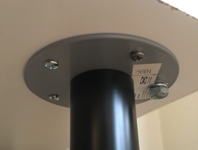
- Next was attaching the Olov legs. Instead of using a flat washer on the M8 bolt used to attach the Godmorgan legs, I had the idea to use the bracket from the Olov legs. The M8 bolt was a little too big to fit through the screw hole in the Olov bracket, so I used the 5/16” drill bit to open it up.
- Then I attached the Olov bracket by loosely threading in the M8 bolt with a 5/16” split lock washer. I adjusted the positioning of the bracket to make sure the edge was equidistant to the two nearest edges of the melamine board, and then used the supplied screws to attach the bracket. I repeated this for the remaining three Olov legs. Now the base is done.
- Tip – I highly recommend trying different legs than the Olov legs. I ended up having to brace them to sturdy the table.
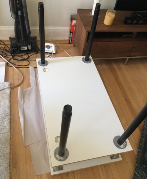
- With the base still upside down, it was a good opportunity to drill the 2.0” wire grommet holes. I decided to put one in each corner on the backside, so that I could use whichever hole was closet to a power outlet.
- I marked a symmetrical location on both sides with a punch and used the 2.0” hole saw to drill through.
- Tip – Use painters tape on both sides of the melamine board where you are drilling to help prevent chipping the finish.
- Before installing the 2.0” inch wire grommets, I added a bit of wood glue to them to make them permanent. You could use E6000 to bond these as well.
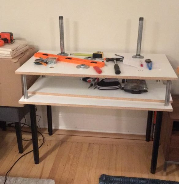
- Before measuring mounting locations for the top shelf, I screwed the flanges on the two 12” galvanized pipes, set them on the base, and then set the shelf on top to try to find a balanced configuration for these mounts. I settled on 9.0” from the two far sides, and 5.0” from the backside. I marked these center locations on top of the base and on the underside of the shelf, and then used the flanges as templates to mark all the fastener locations.
- Before attaching any of the flanges on the shelf, I drilled the two 1.5” holes for the wire grommets. I punched the two locations and used the 1.5” hole saw to drill through. To make the shelf removable, I planned to use nuts and bolts to attach the flanges to the base, and self-tapping wood screws to attach the flanges on the shelf. So the bolt holes on the base would need to be drilled, but the shelf ones do not.
- First, I attached the flanges to the underside of the shelf in the 9”x5” location I had marked using #10 x 0.75” long screws. Next, I assembled the two pipes and flanges onto the flanges now mounted on the shelf, and checked to make sure the flange holes on base end lined up with the ones I marked. Then I used a ¼” drill bit to make the eight holes in the base. I put the shelf back up and inserted all the ¼”-20 x 1.5” bolts to check that everything fit and lined up. (Tip – Use a larger ID pipe and flanges to make it easier for any cables with a plug to pass through.)
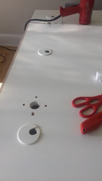
- Before bolting the shelf to the base I finished all four shelf edges with iron-on melamine tape. I cut a length of the tape slightly longer than the edge, lined it up along the edge, and ran the iron slowly across it, back and forth, using the “cotton” setting. (Tip – Don’t plan to run a continuous strip of melamine tape around the entire perimeter. It will crack in the corners.)
- I also finished the two front edges on the base that would be visible when the hinged front panel was open. It’s not necessary to finish any of the other base edges because the plexiglass panels will cover them. On the base, I also ended up installing some edge tape on the 1.5” holes (for the galvanized pipes) with a heat gun to prevent any wire chaffing from the particleboard inside the melamine board. For those same 1.5” holes on the shelf, I applied some wood glue to the 1.5” wire grommets and installed them.
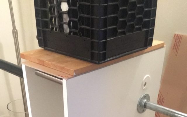
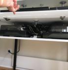
- Now it was time to bond the plexiglass side panels to the base. I started with a 23.75” long side and applied a bead of E6000 adhesive to the upper and lower edge of the two melamine boards. Then I carefully aligned the plexiglass panel and added some weight to the top to prevent any shifting while the adhesive cured over 24 hours. I repeated this for the other 23.75” long side, and the 43.375” long backside, but not the front side.
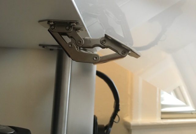
- The 43.375” long front side, that I added the melamine edge tape to, would be a hinged panel, so the attachment would be different. This is also why I chose a thicker plexiglass for this side. The hinge I purchased came with two confusing, but ultimately helpful, templates for mounting. I determined the spacing for the hinges and then used the first template to mark the exact spot on the plaxiglass panel to bond.
- Tip – I recommend using three hinges. One at the far left, one in the center, and one at the far right. This will prevent any gaps along the edges.
- I applied the E6000 to the back of both hinges, carefully aligned them, and used a C-clamp to secure them to the plexiglass while it cured over the next 24 hours. Once cured, I used the second template to attach the panel and hinges to the base with the provided screws.
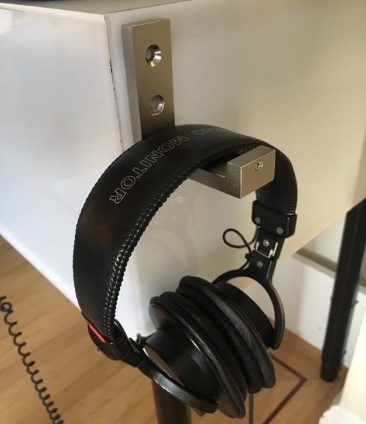
- The last thing to bond is the IKEA Bjarnum hook for my headphones. I chose the right side panel, towards the upper left corner, and bonded it with E6000.
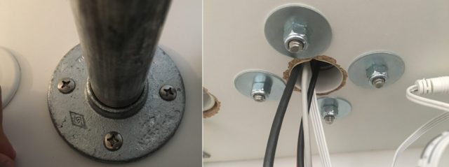
- Next I attached the shelf to the base using eight ¼”-20 x 1.5” bolts, washers, and nylon nuts.
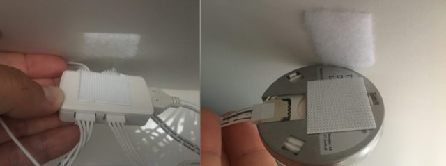
- With the booth pretty much finished, I ran all the wires for the LEDs and attached the lights using adhesive-backed Velcro. I placed three of the lights inside the light box near the center of the three visible panels, and the fourth light on the underside of the shelf.
- Tip – you can also use spools of RGB tape instead – like these on Amazon – to achieve a more even lighting effect in the box.
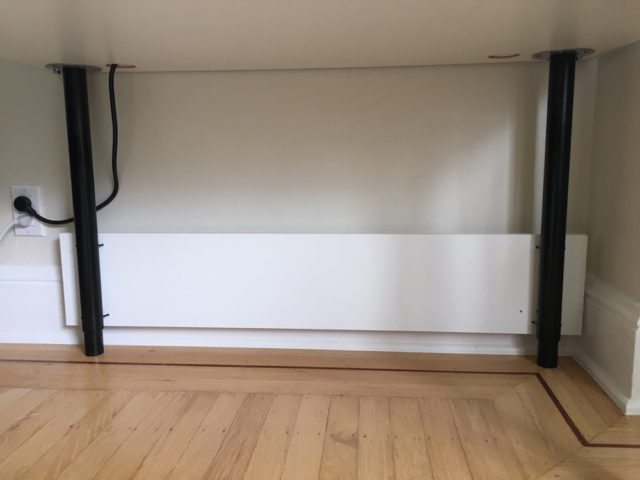
- Thinking the booth was done, I moved it into its place, and leveled the legs to account for my uneven apartment floor. Unfortunately, the booth was wobbly. The source was the threaded attachment of the Olov leg to its mounting bracket. Even when tightly torqued it could still wobble.
- The easiest solution was to brace the legs with a scrap piece of melamine board and some zipties. I measured and marked holes on either side of each leg for the zipties to pass through, drilled, ziptied it, and amazingly it worked really well. I then pulled it back off to finish all the edges with the iron-on melamine edge tape so it looked more presentable, and reinstalled it.
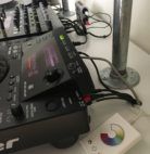
- Finally, it was time to run all the wires and setup my gear:
Have questions about making a lightbox DJ booth of your own? Ask Brian for advice the comments below.
Brian Bentley produces a podcast, The liv dance Podcast, in his spare time when he’s not busy running, cycling, or working as a Vehicle Systems Engineer. He enjoys getting a rise out of fellow DJs by declaring how awesome the “sync” button is.


