In-case you didn’t notice, we have a very active forum with loads of amazing posts and discussions. One of our forum members, fa5ky, published a short tutorial over there on how to change your VCI-100 LEDS to a different color (this applies to almost all equipment). It was so good we decided to post it on the blog! He writes:
You might be wondering why in the world would I take the time to do an almost purely cosmetic mod. Well in my opinion its more then cosmetic- its a major functional upgrade. I had serious problems seeing the LEDS on my regular VCI outdoors or even indoors on a sunny day. This might not seem like a serious problem but when you are jamming out, you want to be able to know what deck is playing, what effects are on etc, at a glance. The boring green and yellow that comes on VCI’s (except the SE version from djtt) are just that, boring, and they don’t have much of a contrast in a daylight setting. So I decided to switch mine to white, blue and red for their contrast and the brightness ( and droooolllzz factor). This tutorial will also come in handy if you just want to replace some dim or dead LEDS. Do this mod at your own risk as I am assuming you have some soldering experience and won’t burn up your circuit board.
REQUIRED GEAR
VCI-100
3mm LEDS-I bought mine from ebay ($6 for 100 leds) and you can choose how many of each color you want. I went with 40 x Blue, 40 x White, and 20 x Red.
Soldering iron and a solder sucker or just a de-soldering iron
Clamp– or extra set of hands to hold the circuit board steady while you remove the LEDS
STEP 1- DIS-ASSEMBLE
First off you need to take your vci-100 apart. If you are doing the arcade mod, now is the perfect time to do this LED mod also since you already have everything dis-assembled. Here is the video on how to do the arcade mod and it basically shows you how to disassemble your VCI in a safe way.
STEP 2- DE_SOLDER
Now it’s time to de-solder your LEDs. you will want to use a clamp or the “helping hand” to keep your circuit boards firmly in place while allowing front and rear access.
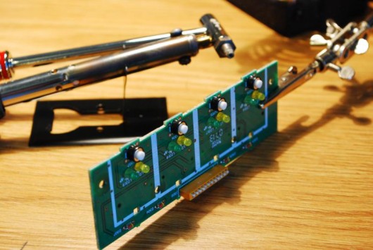
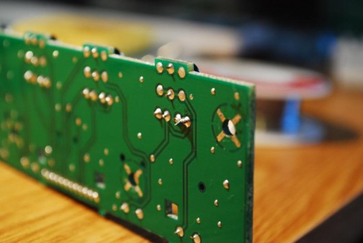
First add solder to the 2 LED contacts on the back of the circuit board.
This will help evenly spread the heat between both contacts so you can remove the LED
While heating up the leads pull on the LED with the pliers
(don’t pull to hard or you might break the led or worst the circuit board, it should come out with some wiggling and a tiny bit of force)
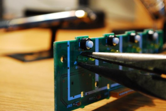
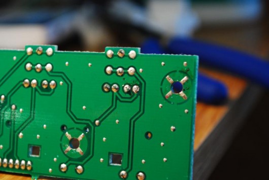
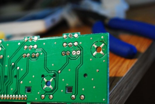
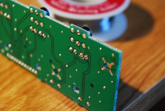
You should be left with this once the LED is removed.
Using a solder sucker or desoldering iron suck up the remaining solder so you can put your new LED in
it should look like the picture bellow
STEP 3- LED REPLACEMENT
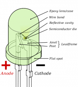
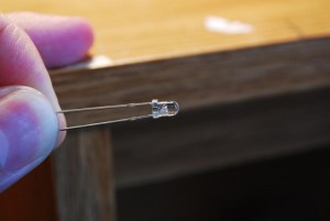
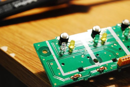
Make sure you cut the LED above small flat section, you may also want to keep the longer leg (positive) so you can identify the sorter leg (negative).Snip the led with a light amount of pressure and bend it to break, otherwise you may end up with a pinched end that is hard to insert. Make sure you have the polarities (positive and negative) correct or it wont light up. Take note of which way the positive and negatives face before you take out your original LED. The following picture will help you identify which side is what.
You should be able to push the LED through the bottom and easily re-solder the connection.
Your done- enjoy the results!


