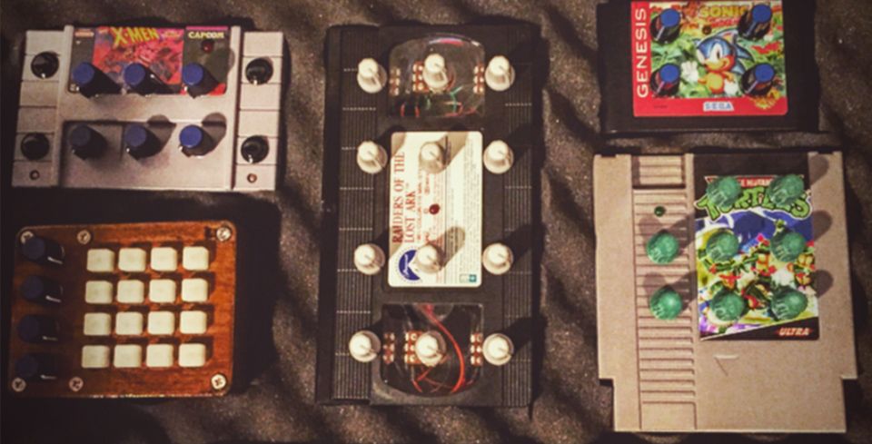
Short on cash, got lots of time, and want/need a new piece of DJ gear custom to your needs? It’s time to go DIY! For about $100 you can build your own MIDI controller. Watch the full how to video from guest contributor Kyle Mohr and read the full construction guide inside.
DIY MIDI Controller Shopping List
First you’ll need to purchase all of your tools and materials. I’ve found the best prices and parts are usually sold on eBay from retailers based in China, but they tend to sellout fast and shipping to the States takes 2-3 weeks (this will, however, give you plenty of time to get your enclosure ready and board programmed). But, to make things easier I’ve provided many links for Amazon and US retailers.
Click the below sections to expand the lists:
PartsEnclosure Finishes
*Note: These are not necessary, but if you have a wood enclosure they help make things look a lot nicer
Note: It will put you way over the $100 budget if you need any of these tools, but if you plan to do more projects in the future they certainly will come in handy and you can always buy them really cheap on eBay and Amazon.
- Soldering Iron
- Rosincore Solder *Any Rosin-core solder should do, this is just what I used
- Soldering Flux
- Drill
- Hobby Files
- Drill Bit set
- 24mm or 1in Spade Bit
- Liquid Electric Tape
- Gorilla Glue
- Wire Cutters
- Plier set
- Small Screw Driver Set
- Hot Glue Gun
- Hot Glue Sticks
- Mini Hack saw
- Box Cutter
- Dremmel with wood cutting bit
- Sandpaper
- BONUS: here’s a great video on tools you need for electronics projects
DESIGN
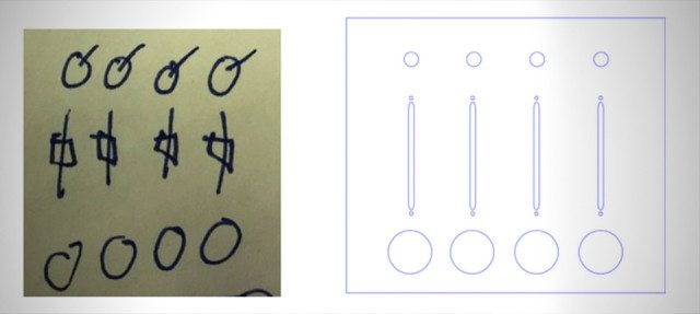
This is my awful drawing on a post-it note, but it suffices as an ideal layout and sketch. I followed it up using Adobe Illustrator to make a to-scale blueprint. Download the PDF and EPS files here. This was designed for 4 potentiometers, 4 faders and 4 arcade buttons, but you can certainly swap them out for other components.
For the buttons, you’ll need a 1 inch or 24mm spade bit and you should aim for using a 5/16 bit for the potentiometers. Make sure to leave plenty of space between your components and do not overcrowd the layout. This will result in broken enclosures and tight areas for soldering. You don’t always have to be this exact, you can always just take a marker and ruler, measure distance between components and make sure to keep the distance the same, and mark up the back or inside of your enclosure with drill/cut spots.
Case Building
Once you’ve finalized your layout its time to “build” or make room for your components. You can use anything for an enclosure: an old VHS tape; plastic lunchbox; retro video game cartridge; a wooden box; or even 3D print your own. The main point of DIY besides saving some money and learning what is really inside your gear, is to customize it to be truly original.
Before you start drilling holes be sure to measure all components and their clearance!
When drilling holes for components in the enclosure, especially with thin wood and plastic, to keep it from cracking when drilling, make sure to choose about 6-7 drill bits from very small to your final size.
For LEDs I always use this guide (look under “Making holes if needed”). This will help you slowly get to your desired size without putting too much tension on the material causing it to crack, chip or break. The key is to drill at slow speeds, and gradually go up to the size you need. If something starts to crack or chip, quickly stop and put your drill direction in reverse. Try using it in reverse for a bit to clean up the cut.
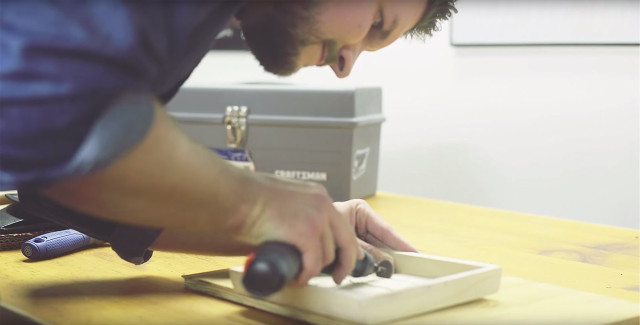
Once you’ve drilled, cut and punched your way through the enclosure its time to clean it up. Don’t worry, it always looks like a hack job. The key is to take your time. Try to drill and mark up the inside (spots people won’t see) and even place a spare board under your enclosure that you can drill into. This also helps to reduce tension on the enclosure.
Now if you used plastic, you’re in luck! You’ve just saved yourself days, seriously! For plastic you can simply use the hobby files to file off any jagged edges, or frayed pieces of plastic, which are blocking the holes.
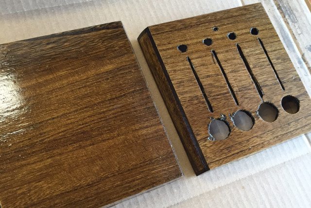
Want to make an awesome wood enclosure?
If you used wood, get ready to go all Ron Swanson on your project. Most cheap wood like we’re using here looks, well, cheap! So how do we class up that piece of junk to look like a custom cut piece of expensive furniture?…Stain!
- I highly recommend pre-stain. It will help the stain spread evenly, especially on cheap/thin wood and prevents spots.
- After 5-15 minutes it’s time to add that stain. Just take a rag, dip in stain and apply to your enclosure. I like to use Dark Walnut. Apply and then immediately remove, and repeat this process a few times. This will give it a more rustic/steampunk look, but if you want something more solid, don’t wipe the stain away, just apply a lot and leave it to dry.
- After a day of drying, apply polyurethane with a brush. Fully coat all sides to protect your enclosure from scratches, and protect, and even strengthen the wood. I suggest brushing it in the direction of the wood grain.
- Let dry for 24hrs, then repeat to your liking. I recommend 3 coats, 24hrs between each coat.
- After the final coat, let dry for 72hrs before adding component parts! This avoids putting my components into a sticky polyurethane mess.
COMPONENTS
Now that you’ve finished your DIY MIDI controller layout and enclosure, it’s time to add your components to the faceplate. Buttons usually just pop in, but some will require a fastener or nut to be placed on the back to secure it (if there is a little resistance, don’t force it, just take your hobby files to it a few times then try again).
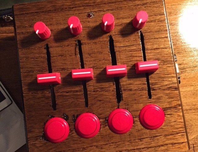
Potentiometer knobs will then be placed in with washers and nuts. These should cover any jagged edges you may have from drilling. Tighten with pliers. For linear potentiometers (aka faders) make sure you have the number 1 (power) on the top. This may vary depending on make and model (feel free to test using a breadboard). 2 is usually your signal, and 3 should be ground. Then secure to the faceplate with your M2 screws.
To protect the components, add your Chroma Caps to faders and pots now (or any off-the-shelf caps as well, we just like those the best).
To add the LED, flip over the faceplate or top of enclosure and put your LED into the hole(s) you drilled for it. You may need to use your hobby file again for this to make sure the LED fits just right. Afterwards, push it through just enough to see the tip on the other side. Using a toothpick as an applicator line the circumference of the LED with Gorilla Glue. Once hardened it will ensure your LED doesn’t fall back into the enclosure. Don’t use hot glue, it may melt the LED’s plastic.
Soldering Your Components
Once the glue on the LED is dry, start the soldering process. This make all of the connections from your components to the circuit board, which will then relay the message to your computer or iOS device (oh yeah, this will also work with your iPhone/iPad)!
First you’ll need your Rosin-core solder (way safer than lead-based solder) – I use and recommend .050”-Diameter 63/37 Rosin-Core Solder.
If you haven’t soldered before there is a wealth of tutorials on YouTube. Here are a few of my favorites. Trust me, its not complicated at all, anyone can do it. Just take your time and pay close attention to what you’re doing.
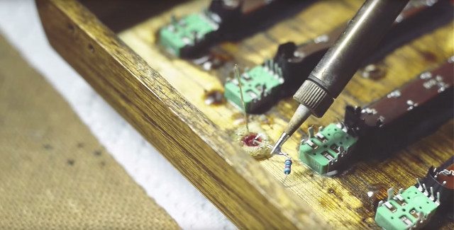
Turn on your soldering iron and let it heat up for a few minutes. Grab your jumper wires. I use these instead of your average spools of wire because they have a single pin at the end instead of braided wire that is quite difficult to push through a hole. They are much more efficient since with normal wire you have to cut, strip, and heat shrink it every time. I also tend to pre-bend them all at 90 degree angles and trim about ¼ off of them to make sure they fit in any enclosure and the Teensy board.
Let’s start from the top and work our way down. First make sure each of your jumper wires will reach from each component to the next, and matching colors is always helpful. I like to use dark colors (black or blue) for the ground line and bright colors (red, orange, yellow) for power while using mild colors (green or white) for the signal line. For D-Shaft potentiometers you want to be certain your pins are on the bottom, this will ensure your knobs fit and that once wired they will be going in the proper direction.
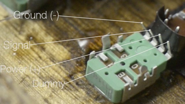
For potentiometers you have 3 lines, ground, active (your analog signal which identifies where the position of your potentiometer is) and your power. They also usually go in that order when looking at the pins, a 4th pin is usually just a dummy pin and will not be used for our project.
Since we only have 1 power and 1 ground point to solder on the Teensy board we need to chain all of our grounds together then all of our power together. Once complete, we need to run that power and ground from the last pot to the first fader, which is soldered and treated as if it was a potentiometer. Follow the guide below.
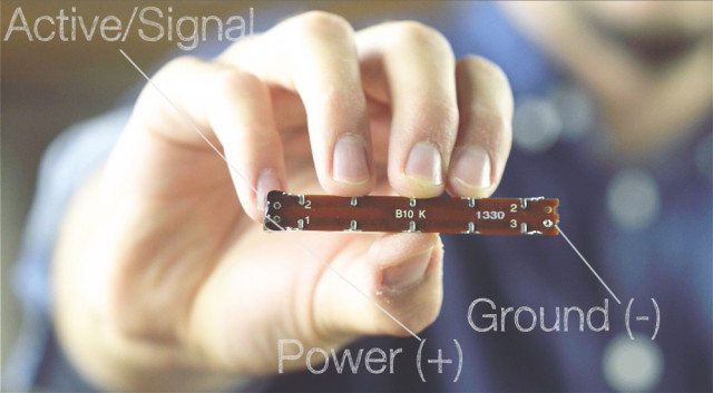
Once that is complete, run the ground only from your last fader to your buttons. The other point on buttons is your active/signal line.
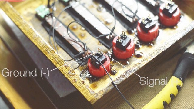
Solder the active line from each component, 1 single wire from each button, knob, and fader. The Teensy board has built in pull-up resistors that we will access using the Sketch we upload when programming the board so we do not need resistors soldered to the buttons active line.
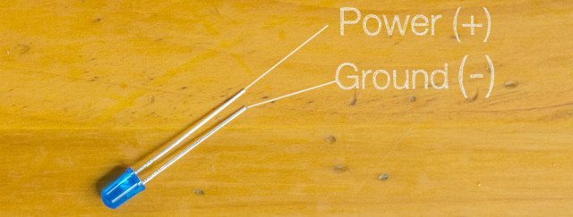
Next, solder a 220 ohm resistor to the (+) powered pin of the LED, this is to ensure it doesn’t blow out from too much power. Then connect the other side of the resistor to a positive pin on the closest pot. We will then solder the short LED pin (ground) to the closest pots ground pin.
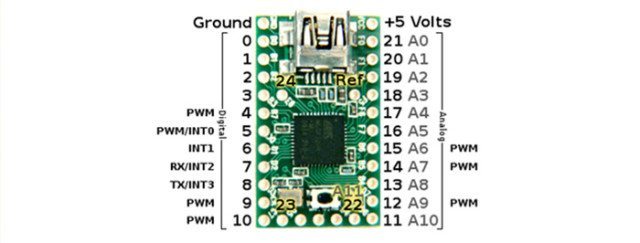
For the last bit of soldering, run the active line from every pot and slider to Analog pins A0 – A7. Where as the active line of each button will be soldered to the Digital pins on the other side of the board B0-B3.
Programming Your DIY MIDI Controller
Setting Up Teensyduino (Arduino + Teensy)
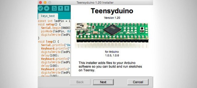
Teensyduino is an add-on for Arduino Uploading Software that enables the Teensy board to be used in the Arduino programming environment. Before we get started you will need to:
- Download Arduino Software *Certain versions of Teensyduino are only compatible with certain versions of the Arduino Software. On the Teensyduino download page this is specified. As of August 2015, “Teensyduino 1.24 supports only Arduino version 1.0.6 and 1.6.1 and 1.6.3 and 1.6.4 and 1.6.5”.
- Download Teensyduino + follow the install instructions on this page (be sure to install all the libraries!)
STEP 1: Plug your Teensy board into the USB port on your computer. After plugged in an orange light on the Teensy should be flashing on and off every second. This is called the ‘blink’ sketch – The Teensy board comes pre-loaded with it.
STEP 2: In the menubar, select Tools->Board->Teensy 2.0.
STEP 3: Also in the menubar, Tools->USB Type->MIDI
STEP 4: Open a sketch file (download mine here). This sketch is set to 8 analog pots (the faders are treated as a knob/pot when it comes to the code) and 4 digital buttons. If you have more knobs or faders, simply change the number here:
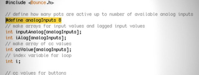
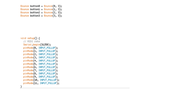
If you wish to add more buttons, there is a little more work, but it isn’t too complicated to fix.
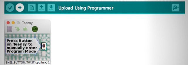
STEP 5: Click the upload button (right arrow) to upload the new code to the Teensy. Since this is the first sketch you uploaded, Arduino will ask you to click the reset button on the Teensy. Click it (see image). After clicked, the sketch should immediately upload.
This code is based off a sketch I was given from fellow DIY MIDI engineer/Musician Otem Rellik. Click the button below to expand the code – it’s long!
The Code#include
// define how many pots are active up to number of available analog inputs
#define analogInputs 8
// make arrays for input values and lagged input values
int inputAnalog[analogInputs];
int iAlag[analogInputs];
// make array of cc values
int ccValue[analogInputs];
// index variable for loop
int i;
// cc values for buttons
int cc_off = 0;
int cc_on = 65;
int cc_super = 127;
// map buttons to cc for button
int cc0 = 51;
int cc1 = 52;
int cc2 = 53;
int cc3 = 54;
Bounce button0 = Bounce(0, 3);
Bounce button1 = Bounce(1, 3);
Bounce button2 = Bounce(2, 3);
Bounce button3 = Bounce(3, 3);
void setup() {
// MIDI rate
Serial.begin(31250);
pinMode(0, INPUT_PULLUP);
pinMode(1, INPUT_PULLUP);
pinMode(2, INPUT_PULLUP);
pinMode(3, INPUT_PULLUP);
pinMode(4, INPUT_PULLUP);
pinMode(5, INPUT_PULLUP);
pinMode(6, INPUT_PULLUP);
pinMode(7, INPUT_PULLUP);
pinMode(8, INPUT_PULLUP);
pinMode(9, INPUT_PULLUP);
pinMode(10, INPUT_PULLUP);
pinMode(11, INPUT_PULLUP);
}
void loop() {
// loop trough active inputs for knobs
for (i=0;i<analoginputs;i++){ // read current value at i-th input inputAnalog[i] = analogRead(i); // if magnitude of difference is 8 or more… if (abs(inputAnalog[i] – iAlag[i]) > 7){
// calc the CC value based on the raw value
ccValue[i] = inputAnalog[i]/8;
// send the MIDI
usbMIDI.sendControlChange(i, ccValue[i], 3);
// set raw reading to lagged array for next comparison
iAlag[i] = inputAnalog[i];
}
delay(5); // limits MIDI messages to reasonable number
}
// Push Button code
button0.update();
button1.update();
button2.update();
button3.update();
if (button0.fallingEdge())
{
usbMIDI.sendControlChange(cc0, cc_on, 3);
}
if (button1.fallingEdge())
{
usbMIDI.sendControlChange(cc1, cc_on, 3);
}
if (button2.fallingEdge())
{
usbMIDI.sendControlChange(cc2, cc_on, 3);
}
if (button3.fallingEdge())
{
usbMIDI.sendControlChange(cc3, cc_on, 3);
}
if (button0.risingEdge())
{
usbMIDI.sendControlChange(cc0, cc_off, 3);
}
if (button1.risingEdge())
{
usbMIDI.sendControlChange(cc1, cc_off, 3);
}
if (button2.risingEdge())
{
usbMIDI.sendControlChange(cc2, cc_off, 3);
}
if (button3.risingEdge())
{
usbMIDI.sendControlChange(cc3, cc_off, 3);
}
}
FINISHING TOUCHES
Before we test our creation, we first need to clean up flux residue with a paper towel and/or Q-tip (for hard to reach areas) and rubbing alcohol. This will remove any materials which could overtime corrode your board and connections.
After that dries it’s time to cover your connections that could potentially touch another and cause a short. You have a few options here: simply tape up any loose connections of bare wire that could touch another or even a metal component part; cover them with hot glue so nothing moves or touches at all; use heat shrink tubing (which doesn’t always fit perfectly); or try liquid electrical tape which comes in a rubber cement style bottle and brush on (which makes covering tight areas a little easier). *If using liquid tape please do so in a well ventilated area.
When the bare wires are covered, plug in your fully-soldered and connected circuit board. The LED should light up and not burn out! Boot up your DAW of choice and make sure you see the Teensy recognized as a MIDI device. Try mapping each component to your DAW and see if a MIDI signal is sent, once you’ve verified, you know you have achieved success!
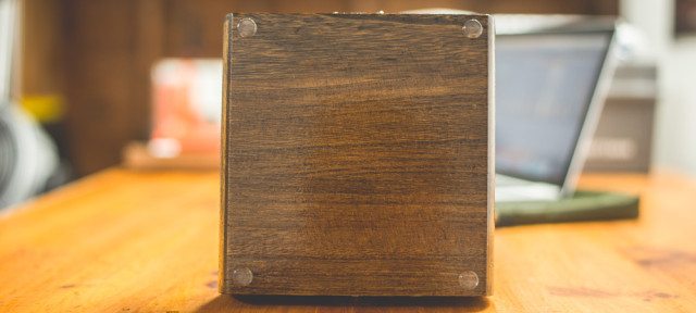
Lastly, it’s time to close up your MIDI controller so it looks less like Frankenstein’s monster. You can use many things to mount the board in your enclosure but I recommend a generous glob of hot glue on the bottom. After it is mounted, plug in your adapter which is mounted to the enclosure, close the lid and seal it up.
Final Product
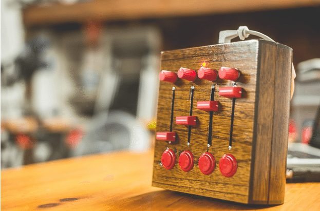
You are now the proud creator of your very first DIY MIDI Controller. Go show it off to the world, and be sure to post pictures of your MIDI controllers in the comments below or tag @DJTechTools on your preferred social network.
This DIY MIDI Controller is loosely a based on the DJ TechTools Midi Fighter 3D and DJTT Midi Fighter Twister.
Guide and design by Kyle Mohr
All video and editing by Alex Medvick


