In this second part of a series on the electrical concepts behind DJ gear, we explore how critical circuits work to give you control over volume, filters, EQ, and more. Get ready to get a little nerdy, and hopefully you’ll come away from this article knowing a bit more about what the knobs and faders on your mixer actually do!
How DJ Gear Creates Sound

Let’s start this piece with a basic overview of how major types of DJ gear actually create sound from their playback mechanisms:
Vinyl (completely analog):
- Small grooves in record cause vibrations in the tonearm.
- The output of turntable is plugged into the phono input on the mixer and amplified out to the speakers
CDJ Setup (both analog and digital)
- Music starts off as a digital audio file (CD, USB drive, SD card)
- Next, the sound card (DAC) in the CDJ converts it to analog signal.
- Mixer takes signals from CDJs, amplifies them, combines them, and adds effects, outputs to speakers. Some mixers may convert to digital, apply digital effects, and convert back to analog.
MIDI/HID Controllers
- The controllers send digital signals to a computer to control parameters in software.
- Digital audio output from the software (some combination of tracks, plus any effects) is then converted to an analog audio signal and send back out via a DAC (either standalone soundcard, or in your controller or external mixer)
Timecode and DVS
- Instead of outputting the position and movement of the controls as digital signals, DVS systems output an audio signal from vinyl records or CDs with a special “timecode” recording on them.
- DJ software takes that audio signal and uses it to control the songs loaded in the software. That digital audio signal is then sent back to a soundcard and outputted to the speakers.
Voltage, Current, and Resistance
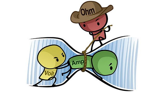
To really dig into how the electrical process works for both MIDI controllers and analog mixers, we need to take a closer look at circuit diagrams – if you’ve never looked at one before, here are the basics elements that you’ll need to understand:
- Voltage (V) is a measure of the energy each electron has – think of it as the height of a hill at which a small pebble is placed. The higher the hill, the more gravitational energy the pebble has, and the faster it will be going once it reaches the bottom of the hill.Voltage is a relative quantity – the height of the hill is measured with respect to the bottom. For an electric circuit, this zero-voltage reference point is called “ground”, and it’s represented by the three-line trapezoid at the bottom of the diagram. Voltage is measured in Volts (V).
- Current (I) is the rate at which electrons flow. If you have a continuous flow of pebbles rolling down the hill, current is the number of pebbles that reach the bottom every second. Current is measured in Amps (A).
- A resistor is a wire that carries electrons. As the electrons flow through the metal wire, they bump into the metal atoms, making them vibrate and heat up. This means that some energy of the electrons is “lost” as heat, so the voltage is lower on the other side of the resistor. Resistance (R) is measured in Ohms (?).
Ohm’s Law: I = V/R
A simple rule that combines the above principles, Ohm’s Law says that the current through a resistor is equal to the voltage difference between the two sides, divided by the resistance of the resistor. Watch the great video above from MAKE if you want to learn more.
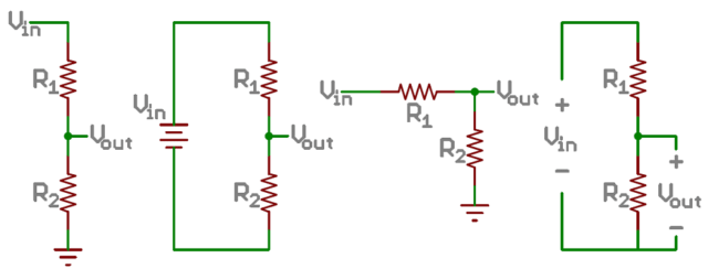
In a voltage divider circuit, there are two resistors connected between a voltage source (ex: the positive terminal of a battery) and ground (the negative terminal of the battery), and you want to know the voltage at the point in between the two resistors.
To make things easier, let’s pretend that the two resistors are actually one big resistor. If the two are connected to each other end-to-end (“in series”), you just add their resistances together.
- To find the current across it, divide the voltage of the battery by the resistance of the combined resistor.
- To find the voltage at the middle point, multiply the current by the resistance of the second resistor. One way to think about this: start at ground (0 Volts), and go “upstream” (against the direction of the current) to find out how much higher the voltage is on the other side of the second resistor. If you have a voltage drop across a resistor in the direction of current flow (by Ohm’s Law), the voltage goes up if you’re “traveling” in the other direction.
- The end result: the voltage in between the two resistors depends on what fraction of the total resistance comes from the second resistor. If the second resistor is small, most of the voltage drop happens across the first resistor, so the middle voltage is very close to 0 V. On the other hand, if the second resistor is much bigger than the first one, not very much of the voltage drop happens across the first resistor, so the middle (output) voltage is very close to the input voltage.
Potentiometers (Linear & Rotary)
The voltage-divider principle is exactly how many of the knobs and faders on DJ gear actual work. They’re potentiometers! Instead of having two resistors with a space in the middle, these controls have a “wiper” that can travel to any point along the resistor.
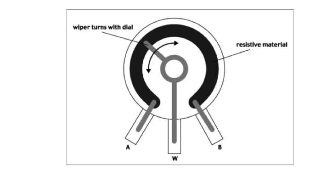
When the wiper is at the top, its voltage is at Vin. When it’s at the bottom, it’s at 0V.
There are two main designs for a potentiometer:
- rotary potentiometer (knobs) – a knob where the resistor remains stationary in the base, and the wiper moves around it as the knob turns.
- linear potentiometer (faders) – where the wiper is attached to a fader that travels across the length of the resistor.

Potentiometers appear on both analog mixers and MIDI controllers, their purpose is different between the two. For example, with a volume fader:
- On a MIDI controller, the output voltage of the fader is sent back to your computer. The software in your computer reads this value, adjusts the volume of the track inside the software, and then sends the audio out through your soundcard.
- On an analog mixer, the actual audio signal is sent through the voltage divider
High and Low Pass Filters
The voltage divider concept is key in understanding the circuits for low- and high-pass filters. For filters, one of the resistors has been replaced with a capacitor.
A capacitor is two conductive plates that can store electrons, separated by an insulating material (sometimes just air) that prevents them from crossing from one side to another. When the frequency of the signal is low, the plate fills up with electrons, and then there’s no more room, so the current stops flowing. However, when the frequency is high, the capacitor fills up and empties so quickly and easily that it’s almost as if the electrons are flowing back and forth through the capacitor.
This means that when the frequency is low, the impedance (similar to resistance) of the capacitor is high, and when the frequency is high, the impedance is low.
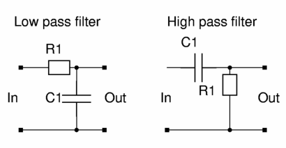
If the capacitor is on the bottom (where R2 used to be), and the frequency is low (a bassy part of a song), the capacitor makes up the majority of the impedance of the circuit, and the voltage output is very close to the input, so the majority of the low frequencies pass through the filter. For high frequencies, the capacitor makes up only a small part of the total impedance of the circuit, so very little of the high frequency signal makes it through the filter.
The high-pass filter is exactly the opposite, because the resistor is on the bottom and the capacitor is on the top. For low frequencies, the capacitor represents most of the impedance, so not much of the signal comes through. High frequencies don’t meet much impedance, and most of the signal passes through.
3-Band EQs
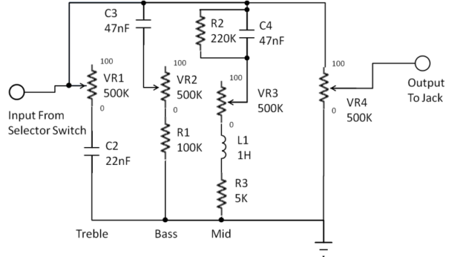
A 3-band equalizer (EQ) is a more complex circuit. The general idea is that the capacitors are used to separate out different parts of the frequency spectrum, and then amplifiers can be used to increase or decrease the volume of the Low, Med, and High components independently. One important difference between filters and EQs is that passive filters can only attenuate (reduce the volume of) the signal, but EQs can be used to amplify the signal.
Amplifier Gain and Clipping (Redlining)
Volume faders are used to finely control what percentage of “full loudness” each channel is at, allowing multiple channels to be mixed together. But what determines “full loudness”? That’s where the Gain/Trim knob comes in.
A Gain knob controls the amplification of the track. An amplifier multiplies an input signal by a certain value in order to produce an output. That output is limited by the amount of power going to the amplifier, so the maximum voltage of the signal is equal to the “rail” voltages that power the amplifier.
If the amplification is too high, the loudest parts of the track will “hit the rails” and get flattened out. This is known as clipping – or redlining -and is bad for the speakers in the long term, and causes a significant drop in audio quality in the short term.
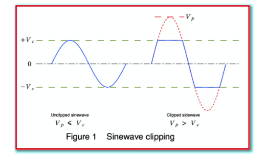
Because most DJ software auto-gains the tracks for us, many digital DJs don’t understand how to set the gain correctly when they plug into an analog DJ mixer. Here’s how to do it properly:
- Skip to the loudest part of the song.
- Turn the Gain knob until the channel VU meter is at 0dB (usually the top green light).
- Adjust the rest of your signal path (master volume, front of house controls, etc) for a volume appropriate for the venue
Electrical Engineering For DJs: Not Required, But Useful
Having an understanding of the inner electrical workings of DJ equipment is not required to play great sets, it does provide some guidance to ensure good sound quality. It’s also a great introduction if you want to start hacking apart your gear or building your own DIY projects.
Have any questions about a specific concept, or want to see another article in this series on a different topic? Let us know in the comments!
Read Part 1 of this series, covering Analog/Digital Audio and Bit + Sample Rates
Ryan Mann is a guest contributor to DJ Techtools, and helps to lead elecTONIC, a student group at UC Berkeley dedicated to promoting electronic music.


